

Microstrip bandpass filters (BPFs) are exploited in diverse areas such as vehicular radar systems and communication applications. Most filters are made of low-temperature co-fired ceramic (LTCC) materials with high dielectric coefficients and high Q factors. However, the higher cost and high firing temperature (850°C) affect integration capabilities, especially at mmWave frequencies. Recently, a lower-cost, lightweight liquid crystal polymer (LCP) material with low loss, low water absorption and deformability has become an alternative material for mmWave applications.
A lower-cost and lightweight transceiver with RF front-end components integrated on a multilayer organic LCP substrate for 60 GHz wireless communication applications was described by Chung et al.1 Broadside-coupled microstrip radial stubs and high-impedance microstrip lines were adopted as quasi-lumped elements for implementation on the three-metal-layer structures and fabricated using multilayer LCP technology to produce an eight-pole filter with an ultra-wide fractional bandwidth (139 percent) and stopband rejection greater than 38.1 dB from 10.57 to 18.0 GHz.2 Lan et al.3 investigated an X-Band flexible bandpass filter on an ultra-thin LCP substrate. Insertion loss was 2.1 dB at the center frequency of 9.4 GHz, and the return loss was better than 20 dB at the designed band. A substrate integrated waveguide (SIW) second-order filter on a thin film LCP substrate at 94 GHz proposed by Zhang et al.4 had a total insertion loss of below 2.6 dB at 94 GHz.
A stepped impedance resonator (SIR) that can push or pull the harmonic bands by adjusting the impedance ratios and electrical lengths of the SIRs in the RF filter design was reported by Makimoto and Yamashita.5 With a specific impedance ratio, stepped impedance structures may have the capacity for suppressing spurious bands. Also, the coupled structure is commonly used to generate the transmission zeros to suppress the harmonic signal. However, it is problematic to realize a high impedance ratio in a coupled line. The low impedance sections with large line widths can reduce the coupling coefficient of a coupled line and result in high insertion loss in the passband.6
In this work, an LCP 24 GHz bandpass filter with a bandwidth of about 4 GHz and an ultra-wide stopband up to 110 GHz is designed and fabricated based on multiple shunt high-impedance lines. A modified tri-section resonator generates the desired passband and achieves a high ratio of the second harmonic frequency to the fundamental frequency. To suppress higher-order harmonics, multiple short-circuit and radial stubs are integrated to provide good impedance matching and generate transmission zeros.
Tri-Section SIR Design Methodology
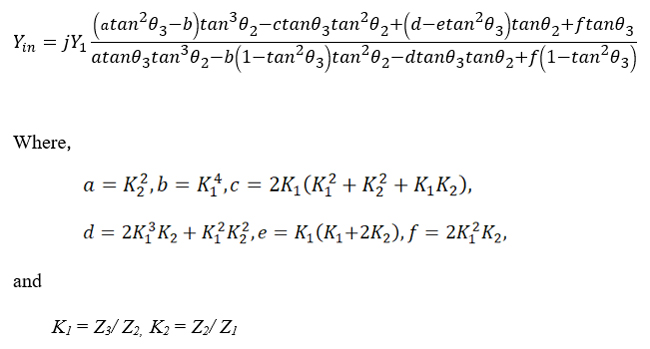
An initial tri-section SIR with a cascade of different characteristic impedances Z1, Z2 and Z3 and electrical lengths θ1, θ2 and θ3 is shown in Figure 1. To provide a more compact size and lower insertion loss, the electrical length of the middle section is limited to half of the conventional tri-section SIR structure. Based on the analysis by Kim et al.7 and under the condition that θ1 = θ2, Equation 1 for the resonant frequency and spurious response is obtained by taking Yin = 0.
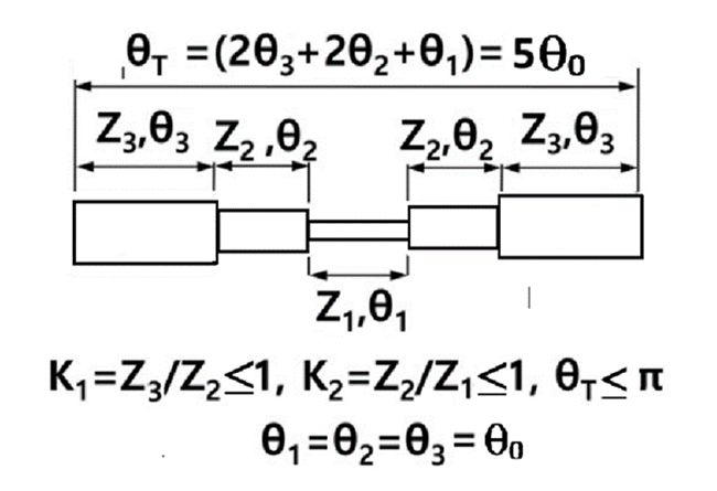
Figure 1 Conventional tri-section SIR structure.
Once section θ3 is chosen and X = tanθ2, the cubic equation of tanθ2 can be further solved as expressed in Equation 2.
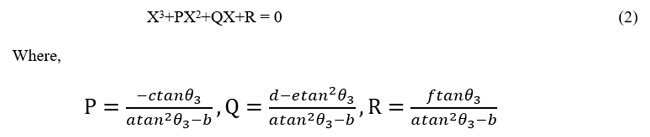
Figure 2 shows the variations of different K2 values with K1 = 1 on ratios of the shifted second harmonic to the resonant frequency fs1/f0 and the third harmonic to the resonant frequency fs2/f0. In the case of K1 = K2 = 1, it is the same as a uniform transmission line, which has a total electrical length of 180 degrees, the second harmonic at 2f0 and the third harmonic at 3f0. To achieve a wide stop band, the second harmonic must be shifted toward a higher frequency. With a fixed value of K1, a lower K2 ratio results in a higher fs2/f0. Different values of K2 can also determine the total electrical length θ in the tri-section SIR structure. It can be concluded that the lower the K1 and K2 ratios, the better the performance.

Figure 2 Ratios of the second harmonic and third harmonic to the fundamental.
Splitting Mechanism
To realize a higher ratio fs1/f0, a higher K1 and a lower K2 ratio are required. Based on a splitting mechanism, a multiple shunt high-impedance line structure to realize a tri-section SIR structure is shown in Figure 3. Two Z2 impedance sections are combined into one section with a Z2/2 impedance. One section with an impedance Z3/4 is equivalent to four Z3 impedance sections.
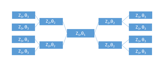
Figure 3 Impedance splitting mechanism.
The equivalent tri-section SIR is shown in Figure 4. In this structure, K1 and K2 are replaced by K1' and K2'. Here, K1' = (Z3/4)/(Z2/2) = Z3/2Z2 and K2' = (Z2/4)/(Z1/2) = Z2/2Z1.
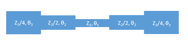
Figure 4 Equivalent tri-section SIR for impedance splitting structure.
Both K1' and K2' are lower than conventional tri-section SIR and provide a high fs1/f0. This structure completely follows the theory of a conventional tri-section SIR. A BPF with a controllable second harmonic band can be further adjusted to achieve a wider stop band. In addition, several open stubs are integrated into the multiple shunt high-impedance line structure to provide transmission zeros at desired locations.
Dual-Feed Coupling Mechanism
In addition to the tri-section resonator, the passband and rejection bands of the filter are affected by the feed structure as well. To implement the split tri-section resonator, a dual-feed coupling mechanism8 is adopted. It is composed of folded open-loop half-wavelength resonators and asymmetrical edge-coupled line-to-line structures. A non-zero-degree feed with mixed coupling is used in the edge-coupled line-to-line structures to produce more transmission zeros near the passband.9
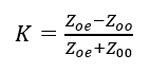
The equivalent circuit of the line-to-line coupling structure is simulated to provide a high-quality factor. A 3D electromagnetic simulator is required for analysis of the asymmetrical edge-coupled line. Parameters such as line width (w), line-to-line gap (s) and substrate thickness (h) are adjusted to obtain the desired even and odd mode impedances. Once the impedances are determined, the coupling coefficient (K) of the ring-to-ring structure is given in Equation 3. More power through the coupled line into the tri-section resonator is expected when the coupling coefficient is close to unity.
24 GHz Bandpass Filter Design
The filter is designed on an LCP substrate with a loss tangent of 0.003, dielectric constant of 3.0 and thickness of 0.1 mm (see Figure 5). To achieve a wide stopband, impedance ratios K1' = 0.45 and K2' = 0.18 are chosen. The corresponding parameters are W1 = 0.05, W2 = W5 = 0.34, W3 = 0.39, W4 = 0.08 and Wgap = Wc = 0.07 mm.
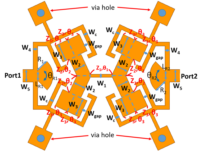
Figure 5 24 GHz bandpass filter with short-circuit and radial stubs.