

Commercial aircraft weather protected radar radome certification and re-certification of repaired radomes according to the latest RTCA DO213A-Change 1A can be time-consuming in antenna pattern tests. Test systems based on three test methods, far-field, compact range and near-field (NF), have been developed to meet the requirements in the past.1-3 However, some of these systems require improvements to comply with the latest version of RTCA DO213A Change 1A requirements, particularly with the λ/4 distance shift in test distance for the NF test methods. This paper introduces a unique, fully compliant spherical near-field (SNF) test system that meets accuracy requirements and maintains range efficiency.
DESIGN CONSIDERATIONS
The SNF test method is chosen based on the required antenna under test (AUT) test volume and the available test space for this project. However, the SNF method is time-intensive due to the need to measure the required number of test points on the NF scan surface given by the Nyquist sampling theorem:
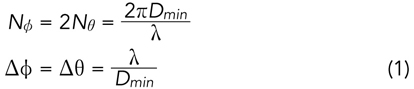
The test system must also adapt to three different sizes of commercial aircraft radomes and accommodate test frequencies at 9.333 and 9.345 GHz. The largest radome will need the Dmin at 2.2 m to fit. When λ at 9.5 GHz is chosen to calculate the sampling points, an angular sampling increment of ΔΦ=Δθ=0.8 degrees is required to be the common denominator to scan the sampling area. A total of 202,500 test points will need to be tested if the entire 4π solid angle is scanned in the SNF test method, which will take too long. Design parameters of the test range subsystems are considered to eliminate redundant pattern tests, thus allowing for optimal performance. Additionally, the AUT properties are utilized to shorten the test time.
Test Range Distance
In selecting test range distance, consideration is given to the minimum separation of 2λ plus the required λ/4 distance shift, which is feasible to meet in the X-Band frequency range. The probe antennas shall always be clear of the largest radome with additional test distance to meet the minimum separation. Predominantly, this test system’s design is motivated to maximize test length to minimize the probe to AUT coupling to a negligible error, such that a λ/4 distance shift can be proven unnecessary, thus saving test time. Therefore, a nominal test distance of 2.5 m is chosen.
Anechoic Chamber
An anechoic chamber with shield-to-shield dimensions of 6.5 (L) × 6.5 (W) × 6.1 m (H) is installed to host the SNF test system and the AUT positioners. The anechoic chamber is treated with microwave absorbers to provide a floor with a reflection noise of less than -50 dB inside a 2.5 m diameter quiet zone at the center of the test range. A monorail hoist system is used to allow easy placement of the radome on the positioners.
AUT Positioners
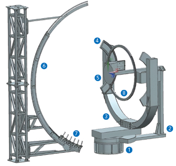
Figure 1 AUT and probe positioner subsystems.
In designing the AUT positioner subsystem, as seen in Figure 1, considerations are given to allow the SNF system scan areas and the panel antenna to be fixed throughout the test sequence. Thus, the relative angular position change between the radome and the panel antenna is implemented by changing the orientation of the radome instead of that of the panel antenna. This positioning subsystem consists of the following seven-motion axes:
1.Azimuth Positioner 1, SNF Azimuth Scan Axis (±180 degrees)
2.Azimuth Positioner 2, Radome Azimuth α Axis (±100 degrees)
3.Elevation Positioner, Radome EL ε Axis (±30 degrees)
4.Radome Roll Positioner, Radome γ Axis (±30 degrees)
5.Radome Longitudinal Linear Positioner (0 to 500 mm)
6.Panel Antenna Azimuth Over-Range Lock
7.Panel Antenna Azimuth Over-Range Counter-Act.
Axes (6) and (7) are the compensating axes that allow the radome to move to the extreme azimuth angular position while allowing the panel antenna to remain in its original center.