12-Channel Probe Subsystem
To expedite the SNF data acquisition, six dual polarized X-Band circular waveguide probes are employed with a high speed electronic switch to collect data from 12 RF channels simultaneously. The probe positioner, as shown in Figure 2, has the following motions:
1. Elevation Slide Positioner, SNF Elevation Scan Axis (±80 degrees)
2. Radial Linear Slide, λ/4 Test Distance Shift (0 to 50 mm)
Notably, the RF absorbers are kept at a distance from the aperture of the six low-directivity dual polarized probes to avoid temperature and humidity variations. Changing RF absorber properties can affect the probe’s calibrated path loss, which negatively affects the SNF system’s stability.
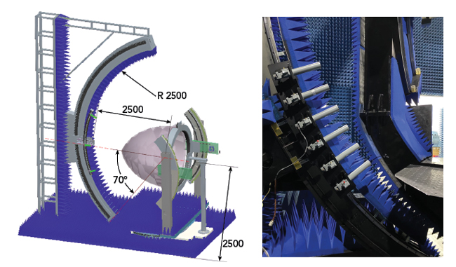
Figure 2 Probe scanning positioner subsystems.
Coordinate System Conversions
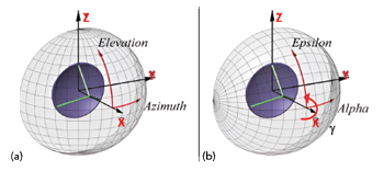
Figure 3 Panel antenna in (a) EL/AZ (θ/Φ) gimbal system and (b) AZ/EL (ε/α) gimbal system.
The radome test labs are rarely equipped with the EL/AZ or AZ/EL panel antenna gimbals installed in commercial aircraft nose cones. Using the radome positioner to simulate relative angular motions will result in the opposite coordinate system. For example, an EL/AZ radome positioning system will simulate a relative coordinate system as if there were an AZ/EL gimbal system for the panel antenna. If one wishes to provide a radome positioning system to simulate radome testing for both EL/AZ and AZ/EL gimbal systems for the panel antenna, a roll axis shall be added as shown in Figure 3.
The EL/AZ radome positioner, as shown in Figure 1, intrinsically simulates only the AZ/EL gimbal coordinates in Figure 3(b). Using the roll axis γ, the conversion to the EL/AZ gimbal coordinate system can be calculated using a set of coordinate transformations. In the EL/AZ (θ/Φ) gimbal coordinate system:

In AZ/EL (ε/α) gimbal systems with an added roll axis γ inside of the elevation axis:


By requiring that the polarization of the panel antenna be kept the same as that of the given (θ,Φ) in EL/AZ gimbal, one can obtain the following three unique solutions of (α,ε,γ):




Figure 4 RF subsystem diagram.
A positioning table can be established to allow fast implementation of (α,ε,γ) to simulate the required (θ,Φ) gimbal orientation. Thus, the AUT positioning system design can implement both EL/AZ and AZ/EL gimbal coordinate systems.
RF Subsystem
Figure 4 shows the RF subsystem of the test range. The directional coupler closest to the AUT measures the reflection from the radome, while the second directional coupler is used to measure the reference input power. An RF power amplifier is used in the input port to boost the system’s dynamic range, thus allowing faster data acquisition. This RF subsystem has a signal dynamic range of less than 80 dB.
Test System Control and NF2FF Software
Positioner controllers and system software, including the NF2FF transformation package, are provided by Nanjing MJK Engineering Co. LTD.
SYSTEM PERFORMANCE EVALUATIONS
Figure 5 shows the four mechanical setups for one radome-off and three radome-on RF performance evaluations to prove the validity and compliance of the installed SNF test system.
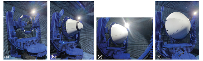
Figure 5 AUT Setups: (a) radome-off with panel antenna, (b) radome-on with smaller radome, (c) radome-on with larger radome and (d) radome-on with the largest radome.
Scan Surface Truncation and Error Considerations
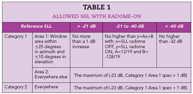
To expedite the SNF data acquisition, a partial scan surface shall be chosen to include a very high percentage of the AUT energy, so no sidelobe levels (SLL) above -33 dB shall appear. Since the AUT is a high gain antenna, a small portion of the solid angle is required for both radome-on and -off configurations. Table 1 shows the required SLL and its allowable variation in azimuth and elevation patterns.
A scan surface with ±40 degrees in azimuth and ±28.8 degrees in elevation is chosen for this purpose. It is verified by re-scanning the AUT using the scan surface ±60 degrees in azimuth and ±38.4 degrees in elevation.