
Computer simulation is essential for the rapid design of efficient RF and microwave components. Not only can ‘what if?’ questions be posed and answered—sometimes in seconds—but once a viable design concept has been identified it can be optimized to achieve cost and performance targets.
To facilitate this, parametric modeling has been introduced as a standard feature in the latest release of Vector Fields’ Concerto electromagnetic design package, Series 6. This feature is further supported by enhanced optimization tools specifically aimed at the type of objective functions required for RF and microwave systems.
In this article, two applications are discussed to highlight the way in which the new software can speed virtual prototyping: antenna diversity and coaxial connector design. The Finite Difference Time Domain method is used for these examples, but Series 6 also includes the options of Finite Element and Method of Moment analysis methods that operate from the same model, providing designers with choices of solver to speed certain simulations, such as cavity modeling or antenna installed performance.
0Optimizing Antenna Diversity
Minimizing coupling between elements of an antenna array intended to provide spatial or polarization diversity provides a topical demonstration of the new tools. Increasingly in wireless applications, multiple antennas are being used to improve performance. However, this depends on the antennas performing independently, and simply moving the antennas apart to improve isolation is not an option in most cases.
In the example design consisting of a pair of planar inverted-F antennas (PIFA) sited in close proximity (see Figure 1), the individual antenna dimensions have been optimized for 5 GHz operation. This structure was selected to achieve a small size without using a high dielectric constant material, to make it less sensitive to material and temperature variations.
The initial design of the PIFA antennas was created using Concerto’s built-in modeler. Most elements are simple shapes, and can be easily drawn with the aid of a new sketching facility that allows primitives to be created using only a mouse, for speed.
In this case the PIFA antenna had been built previously and stored as a library item. The antenna component was imported and copied to make the pair, before a baffle structure was created using the modeler to minimize antenna coupling.
After the initial design had been created, for flexibility of optimization, key dimensions were then redefined as parameters rather than fixed values. This was achieved by simply going back through the recorded list of actions, selecting the relevant drawing operation and changing any value(s) to Model Dimension(s). Once this change was made, the subsequent actions were then automatically re-run to create the new completed model. An initial solution was run using the new Adaptive Meshing option. The mesh was refined until the user’s specified accuracy was achieved. The mesh can also be refined manually by adding extra constraints on cell size anywhere within the model.
A periodic structure of metal baffles was then inserted to minimize the coupling between the antennas. This acts as a filter suppressing the propagation of energy between the PIFA elements. The separation and length of the metal baffles were then set as parameters, which were varied to tune the filter.
In this example the Objective Function was defined to be the minimization of S21. The parameters were given initial values as well as a range of values that each could take (that is, constraints based on maximum possible limits, and to ensure they did not overlap).
The Optimizer Tool was able to automatically find the ‘best’ solution, reducing the coupling by 20 dB, while maintaining good radiation pattern characteristics. The return loss and inter-element coupling are shown in Figure 2, both with and without the baffles in place. The radiation pattern of the design is shown in Figure 3..
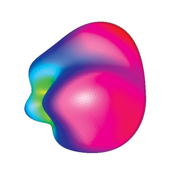
Figure 2 also shows that by adding the periodic structure, the antenna has become slightly detuned. Depending on the design criteria, it may be necessary to include a subsequent optimization to retune the antenna to achieve the required performance.
Coaxial Device Design
Simulation and optimization of coaxial connectors provides another good example of the features of Series 6. A new entry-level version of the software called Concerto AS (axisymmetric) for coaxial device design can be used to simulate complex structures in just a few seconds. Combining this module with Concerto’s optimization tools makes it possible to achieve RF performance targets in minutes.
Concerto AS has a 2D Finite Difference Time Domain solver specifically aimed at coaxial device analysis. The functionality of the tool is tailored around this objective, resulting in an inexpensive product for automating the design of devices such as coaxial connectors, as the following example illustrates.
Concerto AS includes full parametric modeling facilities plus optimization options. For flexibility, models are initially constructed using the same 3D geometric modeler as the full version of the software. This provides a simple upgrade path should a user wish to analyze the effects of non-axisymmetric manufacturing tolerances, for example, or would like to optimize full 3D devices.
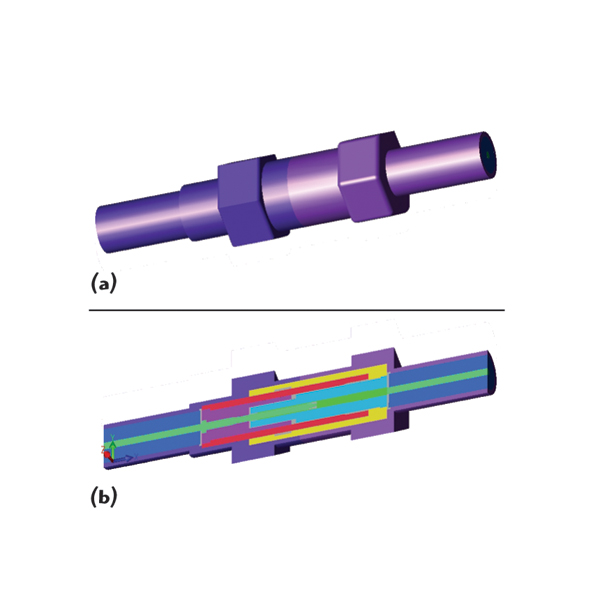
As an example, a coaxial connector (shown in Figure 4) has been created using a macro. By running the macro within the modeler, the various parameters are prompted (see Figure 5), after which the model is created. This allows manual design studies to be performed quickly and easily.
Creation of the macro is straightforward, and is usually achieved by first building the model using the 3D modeler facilities, and saving the list of commands into a file. This can immediately be used as a macro file, and all the commands can be replayed by loading the file into the modeler. The macro file can be further edited by the user to add commands or controls, if the application is likely to occur routinely.
The parameters are defined as described earlier, but this time are used within the macro file as a way to prompt the user for values each time the macro is run. In this way, it takes little or no expertise to run a whole series of solutions just by giving the appropriate values.
Again, the user can employ the Optimization Tool to automate the process of finding the best solution within a given range of parameter values. After having created the initial model, the simulator is launched and the Optimizer Tool selected, thus taking advantage of the new facility offered by Series 6 to set design goals for several parameters simultaneously. The Objective Function is defined (in this case minimizing S11 over the 0.1 to 11 GHz frequency range), and the four variables are all allowed to change, each with a different range of allowed values. The initial and final plots of S11 are shown in Figure 6.
The 2D simulation approach used means that each solution is extremely fast, taking typically four seconds for each optimization step in this particular example. This means that optimizing a number of variables is perfectly feasible (compared with the time that might be required for a 3D simulation). A wide variable space can also be searched to get an optimal solution. After this is found, a few final optimization steps with the inclusion of small 3D features can then be performed to obtain the best solution—even for 3D structures.
Conclusion
With Concerto Series 6, new features make the creation and optimization of real structures both practical and fast. A new sketching facility, context sensitive menus, and the ability to store and re-load library items (including those created in other CAD systems) all help to speed the model creation process, and makes it particularly easy for designers who routinely create variations of similar products, such as antennas.
For full 3D structures, parameterization combined with automatic, multi-goal optimization, allow users to reduce costly design iteration cycles, and achieve the optimal solution much faster. In addition, for large analyses, sophisticated Pause, Freeze and Resume functions provide users with control over their PC.
Also, a new choice of solvers—all working from the same model—provides the best tool for each application. This choice extends to a new 2D version of the FDTD solver aimed at axisymmetric devices such as coaxial connectors, providing an upgradeable entry point to advanced electromagnetic virtual prototyping that can create and optimize designs in a matter of minutes.
Vector Fields Ltd., Oxford, UK +44 (0)1865 370151, e-mail: info@vectorfields.co.uk; Vector Fields Inc., Aurora, IL (630) 851-1734, e-mail: info@vectorfields.com,www.vectorfields.com. Vector Fields is a Cobham group company. RS No. 300
| |