
Waveguide polarizers are often used in radar and communication systems operating at microwave and mmWave frequencies. When a circular polarizer is paired with a suitable antenna, such as a conical horn or a feed horn, it enables the transmission and reception of circularly polarized waveforms. System designers can benefit from understanding how polarizers work and how their performance is commonly described and measured.
Circular waveguide polarizers are passive components that accept linearly polarized input signals. They produce output waveforms with circular or near-circular polarization. The output polarization is generally not circular but slightly elliptical due to various design compromises or manufacturing limitations. Choosing the best polarizer depends on practical considerations such as the importance of polarization purity, operating bandwidth, size and cost. Figure 1 shows an example of an Eravant V-Band linear-to-circular polarizer operating from 50 to 75 GHz.
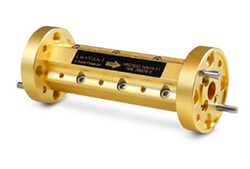
Figure 1 Eravant circular polarizers are commonly used in radar and communication systems.
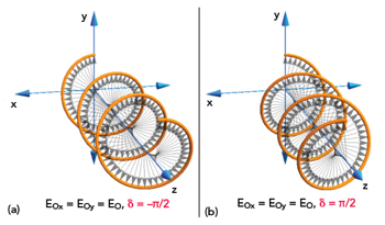
Figure 2 RHCP (a) and LHCP (b) wave propagation of a circularly polarized wave.1
In many applications, a high degree of polarization purity is essential. For example, satellite communication networks often use both right- and left-hand circular polarizations (RHCP and LHCP). Figure 2 shows a vector diagram for the electric field of RHCP (Figure 2a) and LHCP (Figure 2b) waves. The individual electric field vectors, as well as their combined vector, have a constant magnitude, but the phase angle changes with time. This changing phase angle means the electric (and magnetic) field vector rotates in a clockwise direction for RHCP and a counter-clockwise direction for LHCP when viewed along the direction of propagation, the z-axis in Figure 2.
The phase difference of the components of a circularly polarized electromagnetic wave allows a single transmission channel to carry two signals simultaneously. In some applications, good polarization purity is desired for the transmitted signals and the receiving antennas to control interference between the channels. Additionally, instruments like polarimetric radars and radio telescopes often require high levels of polarization purity. In contrast, some applications function well with only moderate polarization purity. For example, many communication systems transmit circular polarization to reduce signal fading. Circularly polarized signals can be received by linearly polarized antennas having vertical, horizontal or diagonal orientations. Limited deviations from circular polarization do not worsen signal fading appreciably.
POLARIZER OPERATION
Many polarizer designs have been realized with various advantages and disadvantages. Figure 3 shows a septum polarizer. This type of polarizer has two rectangular waveguide input ports and a square waveguide output. A thin conducting wall separates the two rectangular waveguide inputs. The wall height decreases over a short distance to increase coupling between the waveguide sections until the signal reaches a single, square waveguide aperture at the output. Applying a signal to one of the inputs produces an RHCP signal at the output. If the signal is applied to the other input, the output is an LHCP signal. This architecture enables septum polarizers to support two communication channels over a single wireless link while sharing a common frequency band.
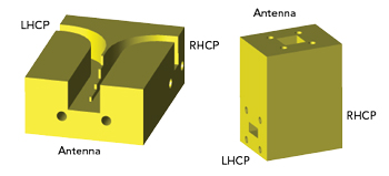
Figure 3 Septum polarizer construction illustration.
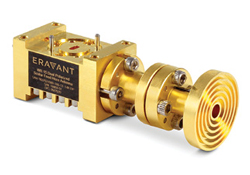
Figure 4 Orthomode transducers can transmit and receive circular polarization.
Circular polarization is generated using an orthomode transducer (OMT). An OMT has two rectangular waveguide ports coupled to a square or circular common port. The H port produces horizontal polarization at the common port, while the V port generates vertical polarization. To obtain circular polarization, signals applied to the H and V ports must have equal amplitude and a phase difference of ±90 degrees when they reach the common port. An example of an Eravant OMT is shown in Figure 4.
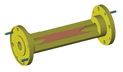
Figure 5 A dielectric vane is used to generate circular polarization.
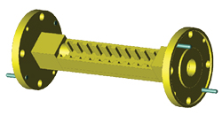
Figure 6 A corrugated waveguide assembly can generate circular polarization.
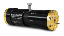
Figure 7 Adjustable polarizers provide RHCP, LHCP and linear polarization.
A variety of single-input polarizers are also available. A typical design approach uses a tapered transition that takes the signal from a rectangular waveguide to a square or circular profile. The polarizing section contains structural features that affect one-half of the applied signal differently than the other half. The two signal components are nominally shifted in phase by ±90 degrees with respect to each other, producing near-circular polarization at the output. Ideally, the two signal components have precisely the same amplitude when they are combined at the output of the polarizer. In practice, impedance mismatches and other limitations cause amplitude and phase imbalances that impact polarization purity.
A variety of phase-shifting structures can be employed to achieve the desired polarization outcome. A typical configuration of this architecture is shown in Figure 5. The illustration of this approach has a dielectric vane oriented at approximately 45 degrees with respect to the input electric field. Dielectric loading effects will cause one-half of the applied signal to propagate slower than the other half. The difference in signal delay will create a 90-degree phase shift between the two signals when they reach the output of the polarizer.
A square waveguide with corrugated surfaces on opposing walls can also generate circular polarization. The corrugated walls will provide different propagation characteristics than the smooth walls and the output signal will depend on the orientation of the applied signal. When the electric field of the input waveform is oriented at a 45-degree angle with respect to the waveguide walls, half of the applied signal travels at a slower speed than the other half, which will affect the polarization. An illustration of this type of waveguide structure is shown in Figure 6.
Adjustable polarizers enable the user to rotate the polarizing structure. Using this approach, the resulting polarization can be continuously varied among RHCP, LHCP and linear polarization. These types of adjustable polarizers are often utilized in antenna test ranges to match the polarization of the transmitted signal to that of the receiving antenna. Figure 7 shows an example of an adjustable polarizer.
CHARACTERIZING POLARIZER PERFORMANCE
A polarization ellipse is commonly used to indicate the polarization state of an electromagnetic waveform. It is also used to describe the measured performance of a circular polarizer. As the phase angle of an RF signal advances with time, the polarization ellipse traces the magnitude and direction of the E-field vector in an x-y plane. The ellipse has an axial ratio (AR) and a tilt angle (τ), referenced to the x-axis. The direction of rotation is either right- or left-handed.
The AR is equal to or greater than 1. Perfect circular polarization, for which AR = 1, occurs when the magnitude of the E-field vector remains constant over time. Because of its impact on the performance of many radar and communication systems, the AR is an important figure of merit for polarizers and circularly polarized antennas.
Directly measuring the AR usually involves probing the electric field produced by an antenna or a polarizer. The test measures signal strength versus the tilt angle. In many antenna test ranges, AR and τ are measured by rotating a linearly polarized probe antenna while recording the received signal strength. AR is calculated as the ratio of the maximum and minimum E-field measurements.
Another standard test obtains the amplitude and phase of the electric fields measured in two orthogonal directions, typically horizontally and vertically. The measurements produce the complex quantities Eθ and Eφ in spherical coordinates or EX and EY in rectangular coordinates. The method is described in IEEE Standard 149-2021, Recommended Practice for Antenna Measurements.2
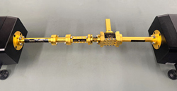
Figure 8 An OMT is an effective polarization filter for measuring the axial ratio.
An effective measurement technique for waveguide polarizers uses an OMT as a linear polarization filter. An example of the setup for this technique is shown in Figure 8. The V port is terminated with a matched load to absorb the signal component entering the OMT’s common port. During measurements of both EX and EY or, equivalently, S21X and S21Y, the H port remains connected to Port 2 of a vector network analyzer (VNA). The input of the polarizer is connected to Port 1 of the VNA through a rectangular-to-circular waveguide transition. Between measurements of S21X and S21Y, the OMT is disconnected from the polarizer, rotated 90 degrees and reconnected. The procedure ensures phase and amplitude coherence between S21X and S21Y measurements.
For many polarizer designs, the measured AR can be impacted by impedance mismatches. Septum and OMT polarizers are generally less sensitive to load mismatches when compared to those using dielectric vanes or corrugated waveguides. To minimize the effects of source and load mismatches, the rectangular-to-circular waveguide transition connected to the polarizer input should have an internal mode suppressor. The suppressor is usually a thin horizontal vane that absorbs cross-polarized signals reflected by the polarizer or the load, thereby reducing measurement errors caused by standing waves.
CONCLUSION
With radar and communication systems increasingly moving into microwave and mmWave frequencies, waveguide polarizers are seeing more use. Implemented correctly, the phase difference of the components of a circularly polarized electromagnetic wave allows a single transmission channel to carry two signals simultaneously. This improves the spectral efficiency of a wireless signal, enabling higher channel data rates. This article has described the theory and implementation of circular polarization. It has also discussed some of the important parameters that determine the performance of polarizers. In particular, the AR of a waveguide polarizer can significantly impact the performance of radar and communication systems. The article has given insight into understanding what AR represents and how it can be measured accurately to help system designers select the best polarizer for a given application.
References
- “What is Circular Polarization in Antennae?,” Stack Exchange, Drones and Model Aircraft, April 2020, Web: drones.stackexchange.com/questions/120/what-is-circular-polarization-in-antennae.
- “IEEE Recommended Practice for Antenna Measurements,” IEEE Standards Association, February 18, 2022, Web: standards.ieee.org/ieee/149/6667.