

Noise sources and noise analyzers are essential tools for testing and calibrating a wide variety of radar, communication and test systems. They are also vital for characterizing individual components and chip-scale electronic devices. At frequencies from MHz to THz, broadband noise sources are needed to measure the noise performance of amplifiers and receivers. They provide signals for testing digital radios and networks and they frequently support built-in test functions in radars and radiometric receivers. Amplified noise sources are commonly used as jamming signals in electronic countermeasures and emerging applications include gas and material composition detectors and broadband imaging systems.
At mmWave and sub-THz frequencies, electronic noise sources typically use an active device combined with a matching circuit and an attenuator or an isolator to match the output port to a standard impedance or waveguide type. In their most common configuration, electronic noise sources provide two calibrated noise power levels for measuring the performance of receivers and various other types of components and systems. A “hot” noise level is generated when the active device is turned on, while a “cold” noise level is produced when the active device is off.
An ideal noise source generates Gaussian random noise over a flat frequency spectrum with a negligible output mismatch to the reference termination.1-6 Many coaxial and waveguide noise sources are available for mmWave frequencies with many reaching 110 GHz. A summary of representative noise sources from a variety of manufacturers is shown in Table 1.
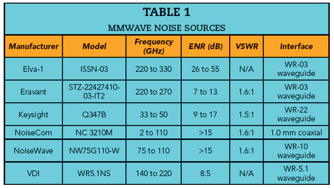
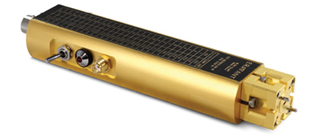
Figure 1 Eravant noise source.
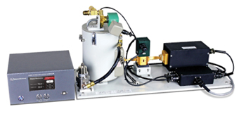
Figure 2 Noise calibration system with reference termination immersed in liquid nitrogen. Source: Maury Microwave.
At higher frequencies, fewer options exist. Fortunately, waveguide noise sources are now increasingly being offered at frequencies exceeding 200 GHz. Figure 1 shows a noise source from Eravant that operates to 270 GHz. Electronic noise sources are commonly used with signal analyzers to perform noise figure measurements. Important specifications include excess noise ratio (ENR) flatness and output return loss. Isolators are often included to improve the output match and stabilize the noise output level.
THERMAL NOISE SOURCES
Thermal radiation sources have been used for calibration since Max Planck presented his theory of heat radiation in 1900. At mmWave and THz frequencies, matched terminations are often cooled with liquid nitrogen or heated with boiling water to produce primary noise references. However, “stem corrections” are typically applied to account for noise contributed by transmission lines and anything else in the signal path between the thermal source and the noise receiver.6 Despite such complications, thermal reference standards are widely used to calibrate noise sources and receivers.
Hot and cold thermal noise standards are available, either individually or integrated into more functional noise calibration systems.7 Cold reference sources typically include a coaxial or waveguide termination placed inside an insulated Dewar flask. The flask is filled with liquid nitrogen maintained at its boiling point. A regulated heater controls the temperature profile of a coaxial or waveguide transmission line that connects the cold termination to a room temperature user interface. An example of this type of precision noise calibration system is shown in Figure 2.
Thermal noise standards are often characterized by an effective noise temperature that is slightly above or below the temperature of the termination. The noise contribution from an element in the signal path may be estimated as shown in Equation 1:

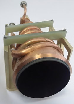
Figure 3 Thermal noise source with conical mmWave absorber. Source: TK Instruments Ltd.
Where:
TE is the temperature of the element
G is the gain factor of the element
To illustrate, a transmission line with a gain factor of 0.99 (0.04 dB attenuation) held at a temperature of 200 K would add 2 degrees to the effective noise temperature of the source. A more rigorous analysis would model the signal path as a cascade of circuit elements with different temperatures.8
Cold thermal sources are also constructed from absorbing materials that are cooled with precision temperature controllers.9 The thermal noise radiated by such structures is typically coupled to a receiver through an antenna with both units operating in a condensation-free environment. Figure 3 shows a thermal noise source with a conical mmWave absorber. The temperature of the absorber is controlled with a circulating fluid.
ELECTRONIC NOISE SOURCES
Some of the earliest electronic noise sources were constructed with gas discharge tubes mounted inside waveguides.10 Gas discharge tubes are still used today, but they are much less common. More recently, laser-induced plasmas in noble gases have produced extremely fast THz signal pulses.11 Optical mixing in photodiodes also produces THz signals. A functional rendition of this idea is shown in Figure 4, where THz pulses are produced when optical power at different wavelengths excites a plasma in a chamber filled with a noble gas. Another type of THz noise generator applies multiple optical signals at different wavelengths to a high speed photodiode.12,13 The photodiode mixes the spontaneous emission noise produced by a super-luminescent LED. While such technologies appear to be in early development stages, they offer hope that THz noise sources suitable for laboratory use are on the horizon.
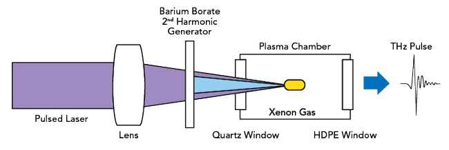
Figure 4 Functional diagram for THz pulses created by optical excitation.
By the late 1970s, solid-state devices started replacing gas discharge tubes.14,15 The sources exploit the shot noise generated in avalanche diodes and other semiconductor devices. Recent developments with avalanche diodes in silicon carbide show promise for improved high frequency performance as signal sources.16 Field-effect transistors of various types can also be used to generate controlled levels of broadband noise.17 At mmWave and sub-THz frequencies, suitable transistors may include GaAs FETs, InP HEMTs and GaN HEMTs. When suitably biased, such devices can produce significant levels of broadband noise.
Noise sources used for noise figure measurements must be turned on and off repeatedly. The source mismatch should be small and more importantly, unchanged between the on and off states. Different noise temperatures are observed depending on whether the source is on (hot) or off (cold). Noise sources are generally characterized by their ENR, as well as a reference termination; either a nominal impedance or a standard waveguide size.
The ENR defines the hot noise level relative to the cold noise level when the source is held at a reference temperature of 290 K.18 The ENR is generally a frequency-dependent quantity. For noise figure measurements and many other applications, the ENR should be as flat as possible and the source mismatch should be as small as possible.
The ENR is an important consideration when choosing a noise source. As a rule of thumb, a noise source is suitable for measurements of noise figures that are up to the ENR value plus about 10 dB.19 For higher device under test (DUT) noise figures, the difference between measured power levels for the hot and cold noise signals becomes too small to yield accurate results. However, a lower ENR should be used when possible because it tends to avoid overdriving the DUT and the receiver. Available noise sources tend to have ENR values around either 6 or 15 dB.