
Due to the increasing competition in the global wireless communication markets, many wireless terminals, such as mobile phones, personal dispatching assistants (PDA) and laptop computers, are being constructed to integrate more than one communication standard into the same apparatus. This allows the end-users to access different systems that provide various services. Since different communication standards may use different frequency bands, front-end components capable of supporting multiple frequency bands have received much attention.1,2 These front-end components include couplers,3–6 antennas7,8 and bandpass filters (BPF).9–13 In the literature, most multi-band couplers reported can support only two frequency bands3–6 because of the high complexities involved in the design. However, antennas that can be operated in two or more frequency bands are very common.7,8 In this work, the design of multi-band BPFs is the primary interest. Recently, dual-band BPFs have been intensively investigated,9–11 whereas the study of tri-band BPFs, which can support three practical commercial communication bands, is relatively scant.12 Furthermore, a quad-band BPF that can simultaneously support four frequency bands is not yet available.
The most intuitive way of constructing a multi-band component is to build an individual circuit for each frequency band and then combine them in parallel, resulting in a large circuit size. Nevertheless, Miyake, et al.9 have successfully extended the parallel-cascade structure13 (originally proposed for a single-band BPF design) to implement a miniaturized, low temperature, co-fired ceramic dual-band BPF by stacking two stripline filters, one for the 900 MHz band and the other for the 1900 MHz band. Although highly compact, this filter needs extra impedance matching networks at its input/output ports. A more clever way of designing a dual-band BPF is to use resonators whose second resonant frequency can be tuned over a very wide frequency range. Stepped-impedance resonators (SIR), originally proposed by M. Makimoto, et al.,14 possess such a property, and were successfully employed in a dual-band BPF design.10 Alternatively, a dual-band BPF can be created by loading a transmission line with three unequal-length shunt open stubs,11 which yield three transmission zeros. Similarly, a tri-band BPF can be constructed by placing four unequal-length open stubs in shunt to a transmission line,12 resulting in four transmission zeros. Although this idea can be extended to implement a multi-band BPF supporting more than three frequency bands, so far, to the authors’ knowledge, a quad-band BPF has not been reported in the literature. This is probably because too many open stubs will make the filter bulky and because mutual loading effects among the stubs have rendered the quad-band BPF topology impractical. Moreover, since the shunt stubs are open-ended, low frequency and DC signals will not be blocked by these filters,11,12 a property that can be regarded as a drawback.
The aim of this article is to design a quad-band BPF that can pass signals in the 1.57 GHz (GPS L1 channel), 2.45 GHz (ISM), 3.55 GHz (WiMAX) and 5.25 GHz (WLAN) bands. Two quarter-wavelength (λ/4) SIRs, when properly designed, can be combined to form a single resonator that resonates at the four desired frequencies. Because a λ/4 SIR offers a smaller circuit size and a higher third resonant frequency compared with a λ/2 SIR, it is used here as the building blocks of a BPF. In addition, the SIRs are meandered to reduce the size of the fabricated BPF, which measures only 12.3 × 9.1 mm. Since the quadruple-frequency resonators used in the BPF are mutually separated, low frequency and DC signals will be highly attenuated.
Quadruple-frequency Microstrip Resonator Design
A BPF can be constructed by combining resonators with the same resonant frequencies in a proper manner. A resonator, with its four main resonances located at the desired frequencies, can be used as the building block of a quad-band BPF. Such a resonator can be composed of two primary resonators, each of which has its first two resonant frequencies identical to two of the four desired frequencies. The prime resonating structure adopted here is a λ/4 SIR, as shown in Figure 1. The λ/4 SIR consists of two microstripline sections having characteristic impedances Z1 and Z2 and electric lengths θ1 and θ2. One end of the λ/4 SIR is grounded through a via of diameter D. For simplicity, the two resonator sections are assumed to have the same electrical length, that is, θ1 = θ2 = θ0. By neglecting the parasitic effects of the via and the step junction between the two line sections, the parallel resonance condition can be derived as tan2θ0(f) = Z2/Z1 = Rz, from which the resonant frequencies can be determined.14 Here, Rz stands for the impedance ratio. Denote the nth resonant frequency of the SIR by fn; then, for a given fundamental resonant frequency (f1) of a λ/4 SIR, the associated second and third resonant frequencies, respectively, can be written as14

This implies that, for a given f1, the second resonant frequency f2 can be freely designed by choosing an appropriate Rz value for the λ/4 SIR. Furthermore, if both f1 and f2 are given, then f3 is fixed and can be considered spurious.
As mentioned, two dual-frequency SIRs (designated as SIR A and SIR B) are needed in order to construct a quadruple-frequency resonator. Let fA1 = 1.57 GHz and fA2 = 3.55 GHz be the first two resonant frequencies of SIR A; thus, RZA = 2.07 and θ0A (fA1) = 55.2°. Similarly, let fB1 = 2.45 GHz and fB2 = 5.25 GHz be associated with SIR B; RZB should then be 2.42 and θ0B (fB1) = 57.3°. Note that the first spurious resonant frequencies fA3 (6.69 GHz) and fB3 (10.15 GHz) for SIRs A and B, respectively, are both greater than the highest of the four desired frequencies. In this article, the filter circuit is to be designed on a 0.635 mm-thick RT/Duroid 6010 substrate with a dielectric constant of 10.2 and a loss tangent of 0.0023. For SIR A, if Z1 = 30.2 Ω (W1 = 1.4 mm), then Z2 = 62.5Ω (W2 = 0.3 mm). In order to combine SIR B with SIR A, the width and characteristic impedance of the first section of SIR B are set to be the same as those of SIR A. For differentiation purposes, the width and characteristic impedance of the second section of SIR B are denoted by W3 and Z3, respectively. The value of RZB = Z3/Z1 thus leads to Z3 = 72.6Ω (W3 = 0.2 mm). These two SIRs can be combined into a single resonator, as shown in Figure 2, where SIRs A and B share part of the W1-wide section. This common section has a length of L1a, which is measured from the center of the via to the upper edge of the horizontal W1-wide section. Also shown is the 50Ω tapping microstrip that feeds the resonator at the junction of the two SIRs.

Quad-band Microstrip BPF Implementation
Note that the value of L1a must be appropriately selected so as to meet the bandwidth requirements for the four passbands centered at fA1, fB1, fA2 and fB2 in the quad-band BPF design. The fractional bandwidths needed are approximately 3 percent (1557 to 1593 MHz), 4 percent (2400 to 2484 MHz), 8.5 percent (3.4 to 3.7 GHz) and 4 percent (5150 to 5350 MHz), respectively. Using a second-order Butterworth response as the target, the element values for the low pass filter prototype are g0 = g3 = 1 and g1 = g2 = √2. The required external quality factors (defined by Qei = g0g1/Δ with Δ being the 3 dB fractional bandwidth of the filter)15 for these four bands are in general different. Let the external quality factor for the ith resonant frequency be denoted by Qei (i = A1, B1, A2 and B2), which can be computed by10
Moreover, the total input susceptance, looking from the tapping position toward the resonator, is B(f), which can be decomposed into B0(f), BA(f) and BB(f), that is the susceptances looking from the junction of SIRs A and B toward the upper side (toward the via), the left side and the right side of the quadruple-frequency resonator, respectively. The expressions for B0(f), BA(f) and BB(f) are easy to derive and are omitted here for brevity. Nevertheless, the expressions of fdBj (f)/df, j = 0, A, B are listed in Appendix A for completeness. The Qe versus L1a curves, computed using Equation 3 for the four desired center frequencies, are shown in Figure 3, which indicates that Qe decreases with L1a. Hence, the larger the value of L1a, the larger the fractional bandwidth Δ (since Δ = g0g1/Qe). Obviously, the four required lengths of L1a for the four desired passbands may be all different. Among them, the largest L1a value must be selected to ensure that all the four passband bandwidths be greater than or equal to the actual required ones. If an L1a value other than the largest one is chosen, some passband bandwidths will be smaller than needed, thus resulting in partial signal blocking in those particular passbands. Note that in Equation 3 and the associated expressions listed in Appendix A, many factors have been neglected, including the dielectric loss, the conductor loss, the dispersion properties of the microstrip sections in the resonator and the effects of the structural discontinuities. Hence, the aforementioned largest L1a value can only serve as a good start in the optimization process of designing the quad-band BPF and may still have to be fine-tuned in the design.
The geometry of the proposed quad-band BPF is shown in Figure 4, where the two quadruple-frequency resonators are placed back to back with gaps S1 and S2 in the horizontal direction. The upper part of the BPF is the main path for signals around fA1 and fA2, whereas the lower part is for signals around fB1 and fB2. Since the resonators have been bent to reduce the circuit size, the structural parameters (W1, W2, W3, θ 0A(fA1), θ0B(fB1), L1a and so on) may need to be further tuned during the full-wave optimization. For the fi-referenced fractional bandwidths Δi(i = A1, B1, A2 and B2) determined for a selected L1a value, the coupling coefficients between these two resonators can be computed using Mi = Δi√g1g2. Once the values of MI are known, the gaps between these two resonators can be determined through full-wave electromagnetic simulation.15 Figure 5 shows a set of simulated coupling coefficients as functions of the gap S. In the inset of the figure, the structure has been configured to have the same gap S for both the upper and the lower half of the juxtaposed resonators. This can be done by adjusting the individual lengths of L1c and L1d for a fixed L1c+ L1d. Once the required (MA1, MA2) and (MB1, MB2) are obtained for two possibly different values of S, S1 will be equated to the value of S pertaining to (MA1, MA2) and S2 to that pertaining to (MB1, MB2). If this task cannot be achieved, the values of L2e and L3b will have to be varied and another set of simulated coupling-coefficient curves generated. If still not successful, the value of L1a may have to be changed to acquire a different set of Di (thus, a different set of Mi) and search for an appropriate set of gaps (S1 and S2).
Experimental Results
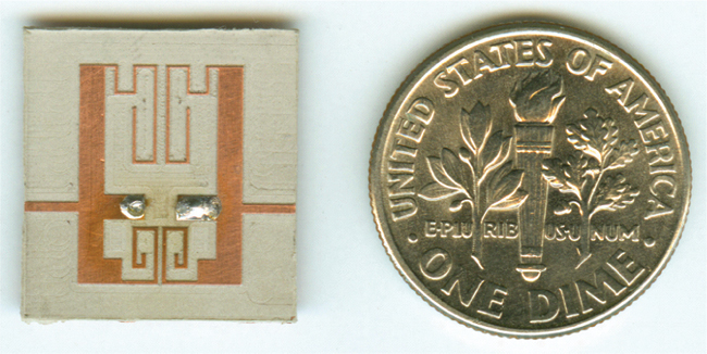
For the fabricated quad-band BPF with the optimized dimensions shown in Table 1, the corresponding coupling coefficients (MA1, MB1, MA2, MB2) are approximately (0.0453, 0.052, 0.062, 0.0794) and the fractional bandwidths (ΔA1, ΔB1, ΔA2, ΔB2), computed from Mi = Δi/√g1g2, are 6.39, 7.4, 8.8 and 11.23 percent. Figure 6 shows the simulated and measured frequency responses of the BPF, which are also summarized in Table 2 for comparison. The measured results agree quite well with those obtained from the simulation done using Ansoft HFSS, a full-wave electromagnetic simulator. The measured 3 dB fractional bandwidths for the four passbands centered at fA1, fB1, fA2 and fB2 are found to be 1510 to 1610 MHz (6.4 percent), 2340 to 2540 MHz (8.2 percent), 3400 to 3710 MHz (8.7 percent) and 4920 to 5560 MHz (12.2 percent), respectively. The minimum insertion losses measured for these four passbands in the same sequence are 1.85, 1.4, 2.0 and 1.06 dB, respectively. The simulated return loss for a single microstrip line-fed quadruple-frequency resonator (half of the BPF structure) is shown in Figure 7 to verify that the designed resonator indeed resonates at the four desired frequencies. A photograph of the fabricated BPF is shown in Figure 8, which illustrates its very small area of only 12.3 × 9.1 mm.

Conclusion
In this article, a new quad-band microstrip bandpass filter (BPF) has been proposed and implemented. The novel resonators composed of two SIRs have been designed to resonate at four desired frequencies, and have been subsequently employed in the BPF design. The circuit size has been greatly reduced by meandering the resonators. The measured frequency responses of the designed BPF have been found to agree with the simulated ones. To the authors’ knowledge, this BPF is the first one reported in the literature that can support four practical frequency bands.
Acknowledgment
This work was supported by the National Science Council, Taiwan, ROC, under grant no. NSC 94-2213-E-018-006.
References
- S.F.R. Chang, W.L. Chen, S.C. Chang, C.K. Tu, C.L. Wei, C.H. Chien, C.H. Tsai, J. Chen and A. Chen, “A Dual-band RF Transceiver for Multi-standard WLAN Applications,” IEEE Transactions on Microwave Theory and Techniques, Vol. 53, No. 3, March 2005, pp. 1048–1055.
- Y.S. Lin, C.C. Liu, K.M. Li and C.H. Chen, “Design of an LTCC Tri-band Transceiver Module for GPRS Mobile Applications,” IEEE Transactions on Microwave Theory and Techniques, Vol. 52, No. 12, December 2004, pp. 2718–2724.
- K.K.M. Cheng and F.L. Wong, “A Novel Approach to the Design and Implementation of Dual-band Compact Planar 90° Branch-line Coupler,” IEEE Transactions on Microwave Theory and Techniques, Vol. 52, No. 11, November 2004, pp. 2458–2463.
- M.J. Park and B. Lee, “Dual-band, Cross-coupled Branch-line Coupler,” IEEE Microwave and Wireless Components Letters, Vol. 15, No. 10, October 2005, pp. 655–657.
- I.H. Lin, M. DeVincents, C. Caloz and T. Itoh, “Arbitrary Dual-band Components Using Composite Right/Left-handed Transmission Lines,” IEEE Transactions on Microwave Theory and Techniques, Vol. 52, No. 4, April 2004, pp. 1142–1149.
- H.K. Jhuang, P.M. Hu, C.I.G. Hsu and C.H. Lee, “A Dual-band Branch-line Coupler Using Quasi-composite Right/Left-handed Transmission Lines,” Microwave Journal, Vol. 49, No. 8, August 2006, pp. 176–184.
- 7. J.Y. Sze, C.I.G. Hsu and J.J. Jiau, “CPW-fed Circular Slot Antenna with Slit Back-patch for 2.4/5 GHz Dual-band Operation,” Electronics Letters, Vol. 42, No. 10, May 2006, pp. 563–564.
- N.C. Karmakar and M.E. Bialkowski, “Circularly Polarized Aperture-coupled Circular Microstrip Patch Antennas for L-band Applications,” IEEE Transactions on Antennas and Propagation, Vol. 47, No. 5, May 1999, pp. 933–940.
- H. Miyake, S. Kitazawa, T. Ishizaki, T. Yamada and Y. Nagatomi, “A Miniaturized Monolithic Dual-band Filter Using Ceramic Lamination Technique for Dual-mode Portable Telephones,” 1997 IEEE MTT-S International Microwave Symposium Digest, Vol. 2, pp. 789–792.
- J.T. Kuo, T.H. Yeh and C.C. Yeh, “Design of Microstrip Bandpass Filters with a Dual-passband Response,” IEEE Transactions on Microwave Theory and Techniques, Vol. 53, No. 4, April 2005, pp. 1331–1337.
- C. Quendo, E. Rius and C. Person, “An Original Topology of Dual-band Filter with Transmission-zeros,” 2003 IEEE MTT-S International Microwave Symposium Digest, Vol. 2, pp. 1093–1096.
- C. Quendo, E. Rius, A. Manchec, Y. Clavet, B. Potelon, J.F. Favennec and C. Person, “Planar Tri-band Filter on Dual Behavior Resonator (DBR),” 2005 European Microwave Conference Digest, Vol. 1, pp. 269–272.
- V. Osipenkov and S.G. Vesnin, “Microwave Filters of Parallel-cascade Structure,” IEEE Transactions on Microwave Theory and Techniques, Vol. 42, No. 7, July 1994, pp. 1360–1367.
- M. Makimoto and S. Yamashita, “Bandpass Filters Using Parallel Coupled Stripline Stepped-impedance Resonators,” IEEE Transactions on Microwave Theory and Techniques, Vol. 28, No. 12, December 1980, pp. 1413–1417.
- J.S. Hong and M.J. Lancaster, Microstrip Filters for RF/Microwave Application, John Wiley & Sons Inc., Hoboken, NJ, 2001.

Chung-I G.Hsu
Chung-I G. Hsu graduated from the National Taipei Institute of Technology, Taiwan, in 1980. He received his MSc degree from the University of Mississippi and his PhD degree from Syracuse University, both in electrical engineering, in 1986 and 1991, respectively. He spent the 1992 spring semester at the microwave and electromagnetics laboratory, Texas A&M University, doing research on the modeling of microstrip antennas. He has been on the faculty of Da-Yeh University since August 1992, where he is presently an associate professor in the department of electrical engineering.

Ching-Her Lee
Ching-Her Lee received his BS degree in electronic engineering and his MS degree in automatic control engineering from Feng-Chia University, Taichung, Taiwan, in 1977 and 1981, respectively, and his PhD degree in electrical engineering from the University of Texas at Arlington, TX, in 1989. From 1981 to 1985, he was on the faculty of the Chin-Yih Institute of Technology, Taichung, Taiwan. In 1990, he joined the National Changhua University of Education, where he is presently dean of the college of engineering. His research interests include planar microwave circuits and microstrip antennas.
He-Kai Jhuang received his BS degree in industrial education from the National Changhua University of Education, Changhua, Taiwan, in 2004, and is currently working toward his MS degree in electronic engineering from the same school. His current interests include microstrip filter design and passive components for wireless communications.
Appendix A
The detailed expressions pertaining to Equation 3 are given as follows:

The term fdBB(f)/df can be obtained from Equation A2 by replacing the subscript A with B. Referring to Figure 2, one obtains

where εr'eff,1 is the effective dielectric constant of the microstripline having a width of W1 and c is the speed of light in free space. Furthermore, θvia(f) = 2πf√εrh/c is an approximate phase correction term representing the phase delay from the via, where h and εr are the height and dielectric constant of the substrate, respectively.