

A compact, low profile, low scattering, low cost and wide-angle passive retrodirective array is based on ordinary microstrip patch antenna structures. Shorting pins and slots are loaded in the patch for gain enhancement and compactness without increasing its profile and electrical size. A rectangular slot improves gain and shorting pins correct the resonant frequency shift caused by the slot. In addition, phase reversal feed technology between elements broadens the beam, which creates a balance between beamwidth and gain. The feed network on the substrate’s bottom layer reduces overall size. Compared with a coplanar feed network, this also reduces scattering, resulting in a wider monostatic RCS beamwidth. Simulation and experimental results show an improved gain of 8.6 dB over commonly available types, with a 3 dB monostatic RCS beamwidth of 114 degrees (simulated) and 104 degrees (measured). It is low profile, with a thickness of about 0.06 the free-space wavelength.
The retrodirective array has attracted much attention because of its simple structure, low cost and automatic beam tracking capability1 when incoming wave information is unknown. This has been extensively investigated and applied in radio frequency identification systems,2 local communication positioning,3-7 automobile collision avoidance systems,8 wireless sensor systems,9 wireless power transmission10 and wireless applications.
The Van Atta array11-12 is a form of retrodirective array whose array elements are symmetrically connected with respect to the center; thus, it has a simple structure. It comprises two essential parts: a radiating structure (antenna) and a feed network. Due to its potential in terms of structure, performance, cost and integration, this array is still being studied and used.
Miao et al.13 proposed a planar passive circularly polarized retrodirective antenna employing low loss and non-dispersive substrate integrated coaxial lines, but the feed lines are frequency dependent. Yan and Shen14 introduced a wide-angle Van Atta array based on a dielectric-filled open-ended waveguide, but this design suffers from a high profile. Other antenna element forms have also been used, such as substrate integrated waveguide,15 microstrip,16-21 Vivaldi22 and slots.23 All, however, have narrow RCS beamwidths or complex structures.
Microstrip patch antennas have been widely studied. They offer significant advantages, including a planar form factor, low cost, lightweight, low profile and ease of fabrication. However, they have low gain. Gain is improved, while keeping the resonant frequency unchanged, by combining a gap with shorting pins.25 This is the approach used here.
In this work, a compact, low profile, low scattering wide-angle four-element Van Atta gain-enhanced array and low loss feed is designed. A prototype four-element array is verified by simulation and monostatic RCS measurements. It demonstrates wide-angle characteristics and scalability.
ANTENNA GEOMETRY
Gain-Improved Microstrip Antenna Element Design
The antenna configuration is shown in Figure 1. The design consists of a conductive patch layer, a substrate layer of Taconic TLY with relative permittivity of εr = 2.2 and thickness of h = 2.032 mm and a ground layer. A rectangular slot is etched at the center of the patch layer to enhance the normal gain.25 A reduction in the resonant frequency of the patch due to the introduction of the slot is compensated by two shorting pins. The pins maintain the original resonant frequency through their shunting effect. Hence, the resonant frequency can be kept constant by proper selection of shorting pin position and gap length. The antenna is fed by a 50 Ω coaxial cable with an inner conductor radius of 0.3 mm. Alternatively, it is feasible to build a planar feed network on the backside. The overall structure is relatively compact and low profile.
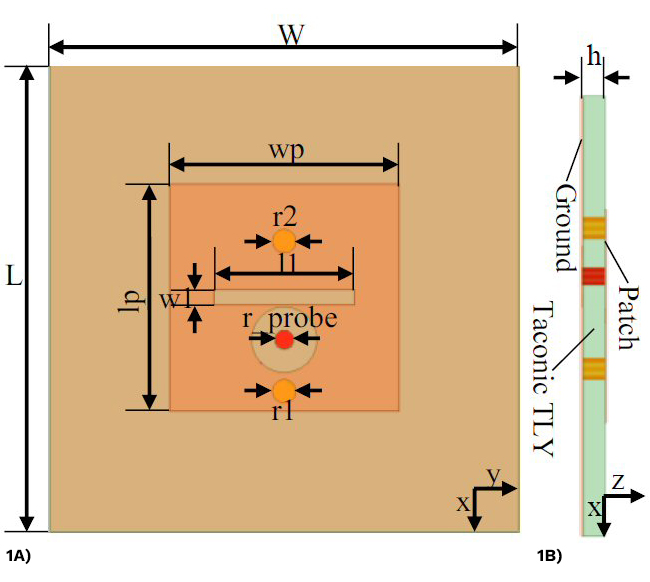
Figure 1 Antenna element configuration: front view (a), side view (b).
The simulated and measured reflection coefficient and peak gain are shown in Figures 2 and 3, respectively. The measured – 10 dB impedance bandwidth is 162 MHz from 5.725 to 5.887 GHz. The measured peak gain is 8.67 dBi with over 95 percent radiation efficiency. The final optimized dimensions listed in Table I are obtained using Ansoft’s High-Frequency Structure Simulator (HFSS) 21.2.
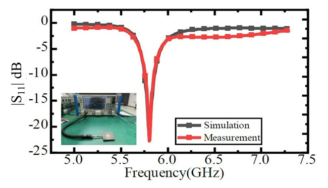
Figure 2 Simulated and measured antenna element reflection coefficients.
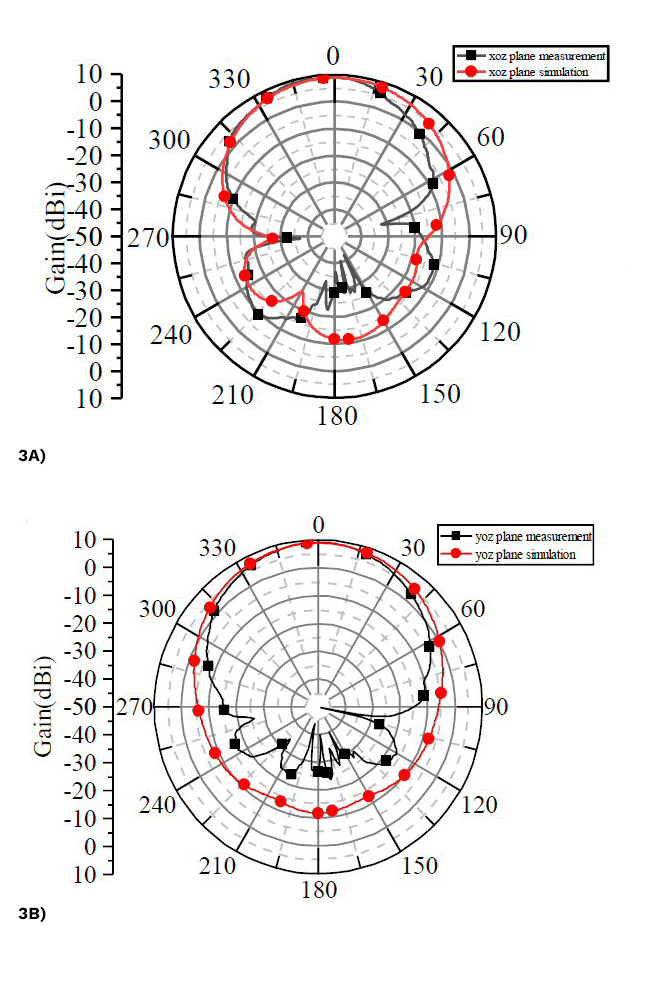
Figure 3 Simulated and measured antenna element radiation patterns at 5.8 GHz: H-plane (a) and E-plane (b).

Relationship between Antenna 3 dB Beamwidth, Aperture, and Gain
The half-power beamwidth is a significant antenna parameter. It determines the scanning angle of the array. Assuming the half-power beamwidth of the antenna is 2θ0.5, a parameter whose value ranges from 65 to 80 degrees, then the relationship for a circular antenna aperture is:

Where η = wavelength; D = antenna diameter.
From Equation (1), the half-power beamwidth of the antenna is inversely proportional to its size. However, there is also a proportional relationship between the gain and the size of an antenna, which is defined as:

Therefore, as the effective area, Ae, of the antenna increases, the gain increases accordingly. The effective area can be further written as follows:

From the above expressions, the relationship between antenna half-power beamwidth and gain is:

It can be concluded from Equation (4) that the half-power beamwidth of the antenna is inversely proportional to the square root of the gain, i.e. the higher the gain of an antenna, the narrower the half-power beamwidth.