
A broadband power amplifier (PA) design is based on a stepped impedance resonator (SIR). Compared with an open circuit microstrip line resonator, the SIR has a better frequency response. Precise harmonic control of the open microstrip line and the SIR matching circuit has the potential for broadband harmonic suppression as well. A multi-frequency method with four frequency points is used to design the matching structure to improve power and bandwidth performance. A broadband high efficiency 1 to 3.8 GHz PA designed using this method yields an output power of 39.7 to 41 dBm with a gain of 9.7 to 11 dB and efficiency greater than 60 percent.
As important components of wireless communication systems, PAs have been the focus of research for many years. The performance of the PA determines the signal strength and working bandwidth of the system. Therefore, improving PA output power and bandwidth has always been a primary research objective.
Many PA design methods have been derived over years of research. With the Doherty PA using active load modulation technology, a peak PA is controlled by input power to achieve an optimal output impedance for high dynamic range operation.1
To improve efficiency, harmonic control PAs have been proposed. The main areas of research employ Class-J2,3 and Class-F4 modes, which are characterized by drain current and voltage waveform shaping with harmonic suppression matching circuits. The efficiency of the PA is improved because the drain current and voltage overlap area is reduced.
The Continuous Class-B/J PA5,6 is an extension of the Class-J mode. The increased factor can be used for broadband matching, and the nonlinear effects of the drain-source capacitor CDS can improve efficiency.7 The filter may be used as a harmonic suppression matching circuit as well.8 Higher harmonics are filtered due to the frequency characteristics of the filter. Most filters, however, have narrow working bandwidths and complicated designs, and their characteristics influence the performance of the PA’s working sideband.
The work presented here is based on the theory of a harmonic control PA with a combined matching structure of an open circuit microstrip resonator and a SIR. The multi-frequency point design method is adopted to achieve harmonic suppression and increase bandwidth. To verify its effectiveness, a broadband PA is designed and fabricated.
THEORETICAL ANALYSIS
Harmonic Control PA
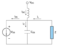
Figure 1 Harmonic control PA circuit.
By controlling the output harmonics of the PA and shaping the output voltage and current waveforms, efficiency can be improved. A Class-F PA is a typical harmonic control power amplifier, nevertheless it is narrowband. Steve C. Cripps proposed a new PA with harmonic control (see Figure 1).9 Its voltage and current waveforms are:
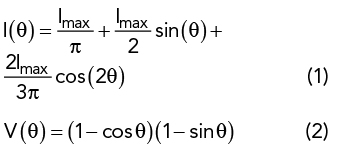
where Imax is the maximum drain current. When only the fundamental and second harmonic are retained, the voltage and current waveforms are approximately half sine waves.10 In Equations (1) and (2), the fundamental and second harmonic impedances are:
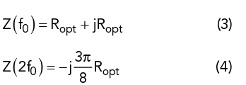
where Ropt=2(VDC−Vk)/Imax, which is the optimal load impedance. VDC is the drain power supply, Vk is the knee voltage and Imax is the maximum drain current. In Equation (4), unlike for a Class-F PA, the second harmonic impedance is reactive, which means that the matching impedance can move around the Smith chart, and so it has the potential to be broadband.
SIR
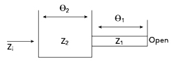
Figure 2 λ/4 SIR.
In this design, a λ/4 SIR11 comprises two transmission lines with different characteristic impedances (see Figure 2). Zi is the input impedance, Z1 and Z2 are the characteristic impedances of the two transmission lines and θ1 and θ2 are the electrical lengths of Z1 and Z2, respectively. Therefore, Zi is:
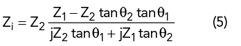
When Zi is equal to zero, the relationship between characteristic impedance and electrical length is:
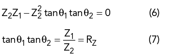
where RZ is a free design parameter.
The input impedance of a λ/4 open-ended stub is determined by its characteristic impedance and electrical length. By comparison, the SIR structure has more free design parameters. Although the SIR structure provides better harmonic suppression, its increased length results in greater signal loss. The combination of a λ/4 open circuit microstrip line and SIR offers higher harmonic suppression while minimizing signal loss.
MATCHING NETWORK CIRCUITS DESIGN
Based on the above theoretical analysis of a harmonic control PA and SIR structure, a multi-frequency point design method is used to realize the combined open circuit microstrip line resonator and SIR matching structure. Four frequency points (f1, f2, f3, f4) are selected.
The influence of higher harmonics in the PA becomes larger as frequency increases, so the SIR provides a wider harmonic suppression bandwidth, but at the cost of increased signal loss. To improve harmonic suppression while minimizing loss, a hybrid circuit structure is used for output matching.
Open circuit microstrip line resonator matching is used at frequencies f1 and f2, while the SIR is designed for matching at frequencies f3 and f4 to further expand the harmonic suppression bandwidth. A center frequency f = 2.4 GHz is selected. To keep low frequency second harmonics from overlapping with the high frequency fundamental and to avoid wide spacing between the four frequencies, the frequency points f1 = 2, f2 = 2.6, f3 = 3.2 and f4 = 3.8 GHz are selected.
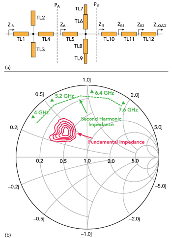
Figure 3 Harmonic control matching circuit (a) and simulated fundamental and second harmonic impedances (b).
The harmonic control matching network is shown in Figure 3a. ZIN is the transistor drain impedance; TL2 and TL3 are open circuit microstrip line resonators; TL6, TL7 and TL8, TL9 are SIRs; TL1, TL4 and TL5 are impedance transformation lines and TL10 is a tuned line.
In this design, only the second harmonic is suppressed. The harmonic suppression circuit design includes two parts. One matches a specific frequency from an open circuit impedance to a short circuit impedance, and the other matches a short circuit impedance to the drain impedance. The open circuit microstrip line resonators are designed at f1 and f2, respectively. TL2 and TL3 match the second harmonic impedance from an open circuit impedance to a short circuit impedance. The electrical lengths of the microstrip lines meet the following requirements:
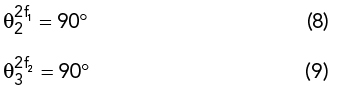
The electrical lengths of θ2 and θ3 are set to λ/4 at frequencies 2f1 and 2f2, respectively. The characteristic impedances Z2 and Z3 of TL2 and TL3 can be designed freely. In this design, Z2 = 39 Ω and Z3 = 25.5 Ω. A terminal short circuit impedance transformation line, TL1, must be added to match the short circuit impedance to the transistor drain impedance. The relationship between the electrical length and impedance of TL1 is:
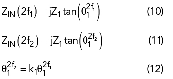
where k1 is defined as f2/f1 in Equation (12) and Z1 is the characteristic impedance of TL1 in Equations (10) and (11).