
A reconfigurable U-slot microstrip patch antenna uses a nematic state liquid crystal (LC) mixture operating at 5 GHz for wireless communications such as Wi-Fi. An external magnetic field from 0 to 1200 Oersted changes the relative permittivity of the LC to adjust the patch resonant frequency. A tuning range of 200 MHz in both measurement and simulation is demonstrated with a maximum gain of 4.05 dB. LC is considered a good candidate for reconfigurable antennas due to its low cost, low profile and performance.
Wireless communication has evolved to become a necessary aspect of our daily lives. At the same time, the growth of the market has led to an increase in the number of standards allocated to systems and terminals operating on different frequency bands. This multiplicity of communication standards typically requires the use of several antennas, each dedicated to a specific band. This, however, implies an increase in the physical size of the system with a significant impact on its cost, energy consumption and complexity. Alternatively, the use of a reconfigurable antenna operating over several frequency bands enables reduced size, power consumption and cost.
A patch antenna has many advantages, such as low weight, moderate cost and ease of manufacture. Nevertheless, for some applications, its bandwidth is too narrow. This limitation can be overcome by making it reconfigurable using lumped elements such as PIN diodes,1 varactor diodes,2,3 RF MEMS switches4 or tunable materials such as ferroelectrics5 and LC.6-13 The possibility of changing the LC dielectric constant in its nematic state through an applied electric or magnetic field has attracted researchers in the microwave community for some decades.
In this work, a patch antenna is designed, using the characteristics of LCs to add reconfigurability. The nematic state LC mixture E7 is injected between the patch antenna and ground. Simulation and measurements demonstrate a tunable range of 200 MHz, with the application of a magnetic field, and a peak gain of 4.05 dB.
PROPERTIES OF LCs
The nematic state of a LC is generally used in microwave and mmWave systems with the external application of an electric or magnetic field to change its dielectric constant. The use of an electric field to change the orientation of LC molecules is, by analogy, equivalent to the use of a magnetic field. In this work, a magnetic field is used to shift the frequency of a patch antenna. To switch on the magnetic field, two magnets are spaced 5 mm on either side; to switch off the magnetic field, the two magnets are removed.
The magnetic field applied to the LC must be greater than 600 Oe.13 To ensure that the molecules of the LC are parallel to the applied magnetic field, the two magnets are positioned 5 mm from both sides of the antenna, where the total magnetic field strength equals 1200 Oe (see Figure 1). The LC molecules are oriented according to the magnetic field applied. When no magnetic field is applied, alignment of the molecules is promoted by covering the lower and upper contact surfaces of the LC layer with a microscopic polyamide film. This achieves the perpendicular permittivity εr⊥. When the applied magnetic field is equal to 1200 Oe, the molecules are oriented in the same direction as the magnetic field, which achieves parallel permittivity εr∥. Martin et al.7 used a foam substrate loaded with LC K15 to obtain a tunable frequency range of 140 MHz from 4.6 to 4.74 GHz and a tuning range of 4 percent, from 5.43 to 5.66 GHz, was achieved using LC E7.13
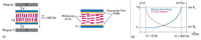
Figure 1 Parallel and perpendicular permittivity (a). Effective permittivity and loss tangent vs. applied bias magnetic field (b).13
PATCH ANTENNA DESIGN
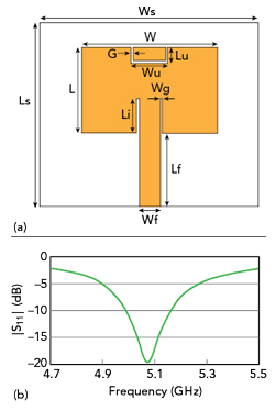
Figure 2 Microstrip patch antenna without LC (a) and simulated |S11| (b).
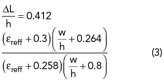
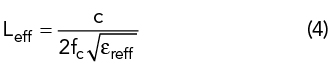
A 5 GHz antenna (see Figure 2a) was designed using Equations 1 through 5.14 The substrate was FR-4, with a relative permittivity εr = 4.4 and a thickness h = 1.6 mm. The patch dimensions were Ls = 30 and Ws = 30 mm. The inset feed Li and gap Wg = 5.7 and 0.2 mm, respectively. A 50 Ω microstrip line (Lf = 2.9 mm; Wf = 12.05 mm) was used to feed the patch on a grounded substrate. Design choices were based on simulations using the CST Studio Suite software. The width, W, was calculated using
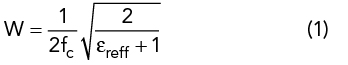
where fc is the center frequency and εreff is the effective permittivity.
εreff is given by
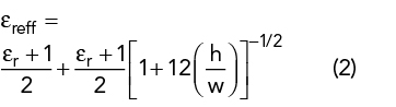
where h is the thickness of the dielectric substrate.
∆L, the extended incremental length of the patch, is calculated from
The effective length is determined by
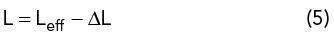
The actual length of the patch is determined by
The final dimensions of the design are listed in Table 1.
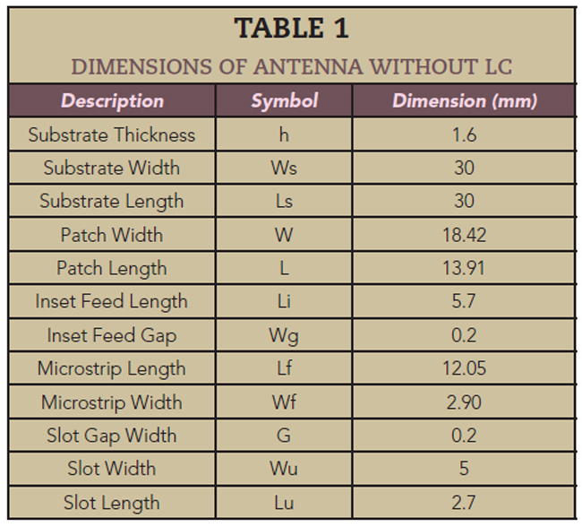
Figure 2b shows the simulated reflection coefficient, where |S11| reaches a value less than -19 dB at the resonant frequency of 5.07 GHz. The simulated radiation patterns without the LC (see Figure 3) show a maximum gain of 2.28 dB and a directivity of 6.80 dBi at 5.07 GHz.
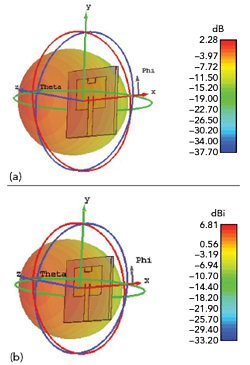
Figure 3 Simulated 3D gain (a) and directivity (b) at the 5.07 GHz resonant frequency.
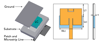
Figure 4 Microstrip patch antenna loaded with LC E7.
The LC E7 mixture in its nematic state, i.e., as a liquid material, is injected into a cavity created above the ground with a depth of 1.5 mm on the substrate, and the upper and lower contact surfaces of the LC layer are covered by a microscopic polyamide film (see Figure 4). Following a parametric study to determine the best position for the cavity, the LC layer is placed under the patch. The dimensions of the LC layer are listed in Table 2 and its electrical characteristics are summarized in Table 3.
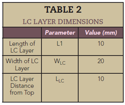

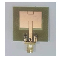
Figure 5 Fabricated prototype antenna.
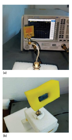
Figure 6 Test set-up for the prototype antenna without (a) and with (b) an applied magnetic field.