
Figure 6 provides information about the external noise picked up by an omnidirectional antenna and then fed to the front-end of the receiver. The different curves ( A to E) within graph represent the following:
A: Atmospheric noise, value exceeded 0.5 percent of the time.
B. Atmospheric noise, value exceeded 99.5 percent of the time.
C. Man-made noise, quiet receiving site.
D. Galactic noise.
E. Median city area man-made noise.
__ Minimum noise level expected.
The intensity of the external noise within the graph is given as equivalent noise figure of a receiver which allows an easy comparison with the noise figure of any given receiver design.
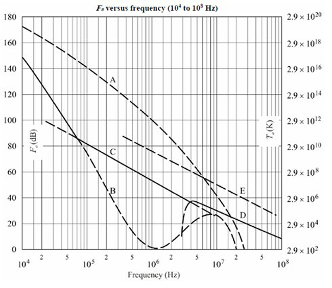
Figure 6 Noise external to an HF receiver.
As a result, it is possible to identify those regions where external noise dominates and exceeds the noise of the receiver. For these cases it is sufficient to design a receiver with a minimum noise figure being some dBs below the external noise figure.
The expectation related to the capabilities of a modern SDR receiver is to be able to adapt to a variety of situations which might have significantly different levels of external noise. The most important factors here are the type of antenna used and especially its geographical location. This means that in silent areas with a minimum of external noise it might be advantageous to have a receiver with a low noise figure, while in noisy areas a receiver with a quite high noise figure might achieve acceptable system performance with respect to sensitivity.
For silent areas, a receiver noise figure of 10 dB (or even below) might be perfect, while for noisy areas noise figures tens of dBs higher may be sufficient. The noise figure and therefore the sensitivity of the total receiver is defined by the combination of noise factor, gain and attenuation within the analog preconditioning (see Figure 1) between the antenna and the ADC.
Gain, Noise and Dynamic Range
In silent areas a high gain with low noise amplifiers may be used between antenna and ADC, while in noisy areas no gain or even an attenuator may be activated. In all cases where no additional hardware filters are inserted between antenna and ADC, the dynamic range of the receiver is then equal to or lower than the dynamic range of the ADC.
If all elements between antenna and ADC are of high quality, the dynamic range of the receiver is equal to that of the ADC and is just shifted up or down to various absolute levels depending on the selected gain. The maximum usable gain is where the strongest signals at the ADC still remain below its Full Scale Level.
An AGC is used to set the gain continuously to this maximum possible level. The time constant for the AGC should be carefully selected to avoid any unwanted gain variations of either the envelopes of the wanted signals or strong interferers or both. The adaption of AGC time constant parameters to suitable values should be made automatically, but in some situations a manual setting may be preferred.
The AGC circuitry for an SDR-based receiver is different than for classical analog receivers. This is necessary to enable the full dynamic capabilities of an SDR design with respect to bandwidth and adaptability to a given and probably fast changing spectrum situation at the antenna. The AGC not only to ensures that the ADC is not overdriven, it must also follow the variations of the wanted signal, for example, an SSB voice signal with an appropriate attack and decay time. These requirements may result in advanced AGC circuitry that separates these two needs and adapts both separately for the best overall characteristic.
Wideband SDR HF Receiver
The main purpose of the wideband receiver path is to monitor a wide instantaneous bandwidth up to the complete HF band. The frequency range may start at 10 kHz, or even lower, and will go up to 30 MHz. It is possible to use a direct sampling SDR concept or transfer the complete HF band to a different frequency level for further processing by using a frequency converter as it is done, for example, within a spectrum analyzer.
The frequency conversion will always lead to an IF frequency well above 30 MHz, typically 70 MHz or even higher. In fact, it will then require an ADC with a higher performance than for direct sampling because the ADC operates on higher frequencies while the expectation for a high dynamic range within a 30 MHz bandwidth does not change.
The phase noise and jitter quality of either the local oscillator or the sampling clock determines the achievable quality for receiver desensitization and selectivity. The requirements with respect spectral purity of the local oscillator used for mixing are higher than those for the sampling clock of a direct sampling concept just based on the different frequency levels. Additionally, the wideband mixing concept struggles to achieve adequate spurious suppression because there are a variety of effects linked to a wideband mixing concept which may lead to unwanted spurious signals in front of the ADC.
These basic facts and their dependencies lead to a direct sampling receiver concept as the best for a wideband HF receiver with the capability to monitor up to 30 MHz instantaneous bandwidth. In the following, this concept will be completed with additional functional blocks to enable the technically best performance which can be achieved today.
Two key elements within the direct sampling concept are the ADC and the spectral purity of the sampling clock. Further elements between the antenna and the ADC either optimize the gain (amplifiers and attenuators) or limit the bandwidth (filters). The intention is to place the input spectrum as best as possible into the operating window of the ADC. The assumption is that all elements between antenna and ADC are chosen to provide a sufficiently high quality that they do not limit the design. As an example, any amplifier between the antenna and ADC must have very high intermodulation performance, beyond the expected performance of the entire receiver. The overall performance of the receiver will then be determined by the setting of gain and filtering between the antenna and the ADC.
If selected, filters are used to suppress strong interferers, which then allows gain to be increased in front of the ADC without exceeding the ADC Full Scale Level. Lowpass and highpass filters are the best choice if the remaining bandwidth is still high enough for the desired use case. For bandwidth to be as high as possible, notch filters tuned to the strongest interferers are a valuable feature.
There are known tuning algorithms that can determine the frequency of discrete interferers, even in cases when the ADC is already overdriven. Such algorithms can be used to automatically tune some notch filters to the strongest discrete interferers present at the antenna. Note that the technology for all preselector filters must be selected to provide sufficiently high intermodulation performance to ensure that they are not the limiting elements of the entire design.
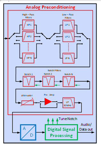
Figure 7 Wideband HF receiver.
Figure 7 shows the complete block diagram of a high performance HF wideband SDR receiver. The signal received by the antenna first passes preselector filters. All elements behind these filters benefit from the existence of these filters. The filters in Figure 7 are arranged in a bandpass configuration built with a combination of highpass and lowpass filters followed by tunable notch filters. The highpass filters can additionally act as protective circuits, i.e., for electrostatic discharge or lightning protection to a certain degree.
The combination of highpass and lowpass filters provides the ability to vary the passband bandwidth while keeping a high selectivity at the edges of the filters, which provides flexibility to adapt to the spectrum situation at the antenna. The notch filters are cascaded and can be tuned fully independent from each other. All filters may use switched inductors and/or switched capacitors to achieve a sufficient tuning range while providing excellent intermodulation performance.
Behind the filters is a settable attenuator, which is in front of a high linearity preamplifier. The amplifier can additionally be bypassed. The attenuator plus the amplifier bypass capability are used to set the gain of the entire signal path between the antenna and the ADC.
The filter and amplifier section provides the analog preconditioning shown in Figure 2. Behind the high-end ADC is the digital processing section. This is likely to be built using field programmable gate array (FPGA) circuits for proving the sampling signal and configurable building blocks for digital signal processing. The digital signal processing starts with some initial digital filters and digital down-conversion. After the digital down-conversion, the sample rate is normally low enough to allow further processing within digital signal processor (DSP) chips.
The current trend for digital signal processing is to avoid dedicated DSP chips and place all signal processing stages within FPGAs. The advantage of operating all signal processing blocks inside an FPGA is that many blocks can be operated fully in parallel. This allows the running of processing blocks, which are responsible for tuning the notch filters, setting the optimum gain and other operations related to preconditioning separate from those blocks that are linked to the waveforms, such as demodulators and audio filters. With this configuration it is possible to set the required gain very quickly while the demodulation process has not even started, enabling the receiver to adapt rapidly to any spectrum situation at the antenna.
The capability to operate many signal processing blocks fully in parallel matches perfectly to a direct sampling SDR design because it also allows running many different user applications in parallel. This opens the way to a flexible receiver product providing, for example, panoramic views, spectrum monitoring, demodulation of various signals and other functions fully in parallel simultaneously.
The only constraint is that all applications operate within the same gain and filter settings and operating window of the ADC. Nevertheless, due to the capability to set, for example, gain very quickly, it is possible to assign different gains and filter settings within a time-sharing concept to different applications as long as the reserved time slots are sufficient.
Narrowband SDR HF Receiver
The concept behind the wideband receiver design is mainly driven by one single key requirement, which is the ability to operate with an instantaneous bandwidth up to the entire HF band. The signal processing stages are not limited to processing either wideband or narrowband signals. This leads to the question, “why might a narrowband receiver have a different concept?” The answer to this question is directly linked to the use case, or in other words: “Where is the receiver operated and what is the situation with respect to noise, interference and frequency offsets between interferers and wanted signals?”
In some use cases strong interferers may come very close to the frequency of wanted signals. The AGC will reduce the gain between antenna and ADC to a value which ensures that the ADC is not overdriven. But if the difference in levels between the wanted signal and the interferer is higher than the dynamic range of the ADC, the total receiver will not be able to find the wanted signal because it is shifted below the sensitivity threshold of the receiver.
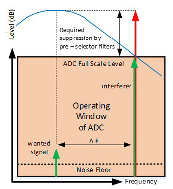
Figure 8 ADC operating window with preselector filters.
The way out of this situation is to suppress the interferer by using filters between the antenna and ADC. The required selectivity and suppression of the filters for this use case is the value in dB for which the difference in levels between wanted signal and the interferer exceeds the ADC dynamic range. As an example, if the dynamic range of the ADC is equal to 100 dB and the interferer is 120 dB above the wanted signal, at least 20 dB suppression of the interferer is needed by the preselector filters (see Figure 8).
The wanted signal (small arrow in green) is close to the sensitivity of the system at the input of the ADC and the strong interferer, in red, is some dBs above the ADC Full Scale Level. The blue curve shows the selectivity of the preselector filters in total. The suppression of the preselector at a frequency offset of ΔF is sufficient in this example to reduce the level of the interferer below the ADC Full Scale Level. The reduced interferer signal (the long arrow in green) and the wanted signal (small arrow in green) are now both within the operation window of the ADC. The frequency offset, ΔF, is the frequency difference between the wanted signal and the closest interferer, which may be beyond the ADC Full Scale. These facts provide clear advice on which concept is best for an SDR HF receiver:
- If the selectivity of the preselector filters is good enough to bring any spectral situation into the operational window of the ADC and the desired sensitivity is still available then a direct sampling concept is usable and is recommended.
- If the selectivity of the preselector filters is not sufficient then an IF sampling concept is a must because the missing sensitivity can only be added within the IF domain.
These two statements emphasize that the choice between a direct sampling concept and an IF sampling concept is based only on the required selectivity between the antenna and the ADC in combination with the capability of the ADC. The flexibility of a direct sampling concept is higher than for an IF sampling concept because the digital signal processing has wider access to the spectrum; therefore, it is recommended to start first with a direct sampling approach and then try to extend its performance to the technological maximum or to the technological need based on the use case by selecting a suitable high-end ADC and high performance preselector filters.
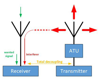
Figure 9 Collocation scenario for the receiver.
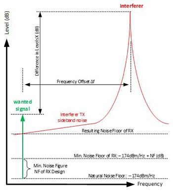
Figure 10 Key parameters for collocated installations.
In cases where the dynamic range in combination with the preselector´s capability is still not sufficient, an IF sampling approach should then be selected. If an IF sampling concept is the only way to fulfill the wanted spectrum requirement, consider that the insertion of an IF filter, as such, will already introduce quite high additional selectivity compared to the preselector. This means that after selecting an IF sampling concept, optimization is possible by either relaxing the ADC performance requirements or those of the preselector filters or both. These steps will help to reduce costs by enabling the use of cheaper key components for the design.
In the following, costs will not be considered and further thoughts about concepts are driven only by trying to maximize the performance to a limit defined by the available technology for key components.
Defining the Data Sheet for a High-End Narrowband SDR HF Receiver
We assume that the planned receiver can provide high sensitivity (if required) while strong interferers may be present simultaneously. Interferers are allowed to come as close as, for example, 10 percent from the tuned center frequency of the receiver which is the case within some collocated installations such as navy ships or coastal stations. Interferers at such small frequency offsets may introduce some external noise to the receiver caused by transmitter sideband noise. This means that a receiver must be able to operate with the high-level interferer being present at the antenna, but at the same time the required sensitivity can be adapted to the external noise caused by the transmitter. This means that the specification for a high-end receiver must consider, or at least assume, the characteristics of the interferer signals and their proximity close to the receiver.
Figure 9 shows that very strong interferers are normally part of the same system installation as the receiver. Ideally the designer of the receiver is also the system designer of the installation including the installed transmitters. This means that the design work should ideally focus on a transceiver concept where the receiver is a part, including the selection and placement of all relevant antennas.
The worst-case scenario for the receiver is when a very low noise transmitter acts as an interferer and the system is operated in a quiet area. For a quiet area, assume that a noise figure of 10 dB should be achievable by the receiver. The required tolerable difference in levels between wanted signals and interferers can be estimated by analyzing key parameters within the system installation. Figure 10 shows the key parameters. Real values are given as basis for further calculations.
For the key parameters in Figure 10 the following values are assumed:
• Frequency Offset ΔF: 10 percent
• Total Decoupling: 15 dB
• Excellent Interferer Tx Sideband Noise: 180 dBc/Hz at 10 percent
• Interferer Transmit Power: 1000 W
The value for the total decoupling between Tx output and Rx input is based on typical parameters for all relevant parts, such as antenna tuning unit (ATU) efficiency, antenna types and distances between antennas within big communication sites. It is known that there may be smaller values for decoupling but these are seen as exceptions.
Sideband noise of the interferer is beyond that of currently fielded transmitters. The reason is that it is assumed that not only SDR receivers but also SDR transmitters will improve over the next several years. With this information some important data at the receiver input can be derived.
The estimated levels for the wanted signal requires some further assumptions for the waveform used that are related to bandwidth and SNR. We choose either A1A (CW) with a bandwidth of 200 Hz or an SSB signal J3E with a bandwidth of 3000 Hz. For both, an SNR of 6 dB is assumed, knowing that A1A signals can be reliably picked up with significantly lower SNR. The reason for using the same SNR is to show the influence of bandwidth only, which allows for an easier comparison of parameters.
• Level of Interferer at Rx input +45 dBm
• Noise Power Density of Interferer at Rx Input: -135 dBm/Hz
• Equivalent Noise Figure of Rx with Interferer: 39 dB
• Noise Figure of Rx without Interferer: 10 dB
• Usable Levels for Wanted Signals without Interferer:
- A1A: -135 dBm or 0.04 µV
- J3E: -135 dBm or 0.04 µV
• Required Levels for Wanted Signals with Interferer:
- A1A: -106 dBm or 1.1 µV
- J3E: -94.2 dBm or 4.4 µV
• Difference in Levels between Interferer and Wanted Signal:
- A1A: 151 dB
- J3E: 139.2 dB
The challenge for the planned receiver concept is now to tolerate a very strong interferer of + 45 dBm at a frequency offset of 10 percent while a wanted SSB signal, which is 139 dB lower, must be demodulated properly. For the reception of A1A, the weak wanted signal is 151 dB lower than the interferer at the antenna. In cases where an A1A signal must be received, this difference in levels increases accordingly if the SNR is less than 6 dB as chosen here.
If it is assumed that in practice a high-end ADC can operate with weak signals 100 dB below the ADC Full Scale Level, we can assume that with some SNR required, the maximum allowed difference in levels between an interferer and a weak wanted is 95 dB maximum. This value is available if the AGC of the receiver can set the gain between the antenna and ADC very precisely and carefully and is now taken as basis for further calculations.
Thoughts about Preselector Filters
Knowing that the preselector must provide the missing suppression of the interferer beyond the 95 dB ADC range leads to a required selectivity of 56 dB at 10 percent offset if the receiver is to pick up narrowband A1A signals. If it is sufficient to operate only J3E signals the required selectivity will be approximately 44 dB at 10 percent. These values required for the preselector filters point to a well-defined high-end design of all elements between antenna and ADC, not only the filter stages as such. The input level of +45 dBm must not lead to any relevant nonlinearity, which is already very difficult to achieve independent from the basic SDR concept for the rest of the receiver.
The preselector must provide an electronically tunable bandpass characteristic through almost the entire HF band from 1.5 to 30 MHz. Below 1.5 MHz it is sufficient to use a 1.5 MHz lowpass filter because in this part of the HF band the interferer scenario is significantly different.
A reasonable limit for an achievable value of selectivity in combination with a sufficiently low insertion loss and a very high power handling capability is typically 20 dB suppression at 10 percent offset for one filter stage. This value for selectivity must also be seen in combination with temperature stability and, finally, the size of the required components such as inductors and capacitors and elements for switching, for example, relays. If the absolute power is lower, a more selective design would be possible, but as previously mentioned, selectivity is not the only important parameter.
The preselector consists of several filters that first divide the entire band into sub-bands. This keeps the complexity of each individual filter within practical limits. The required total selectivity can then be achieved by cascading filter stages with amplifiers in between. These amplifiers must also be of a highly linear design and are combined with attenuators and a switchable bypass to properly adapt to different input spectrums.
The quality of the components between the antenna and ADC, previously called analog preconditioning, is essential for the overall performance of the total receiver. Independent of whether the receiver concept is a direct sampling or an IF sampling concept, the analog preconditioning stages are responsible for reducing unwanted interferers sufficiently enough to allow for linear operation of all following components.
Protecting the mixer within an IF sampling concept is of the same relevance as protecting the ADC within a direct sampling concept. The essential difference between IF sampling and direct sampling is that an IF sampling concept can dive deeper into the noise parts of the spectrum after the preselector filters than a direct sampling concept can. The IF filters provide additional selectivity in front of the ADC suppressing strong interferers beyond the capabilities of the preselector filters. If a “super performing preselector” were possible, a direct sampling concept would be the best choice because it avoids some unwanted additional spurious that may be created in the mixing process. For real preselectors, even high performance ones, an IF sampling concept is necessary beyond a particular limit for strong interferers.
Block Diagram of a High-End SDR HF Receiver
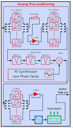
Figure 11 High-end SDR receiver block diagram.
If the data sheet previously defined for a high-end narrowband SDR HF receiver is to be realized, then an IF sampling concept is the best choice. In Figure 11 a block diagram for such a high-end SDR receiver is shown. The block diagram shows all required key elements with the capability to receive very narrowband signals, e.g. A1A with 200 Hz bandwidth even in the presence of strong interferers.
The antenna signal first passes a two-stage preselector built with tunable bandpass filters. The bandpass filters cover the HF band from 1.5 up to 30 MHz. The frequency range below 1.5 MHz can use a 1.5 MHz lowpass filter instead of the bandpass filters, not shown in the block diagram.