
The preselector uses two cascaded filter stages with a combination of attenuators and amplifiers in between. With deactivated attenuators and activated amplifiers, a total noise figure of 13 dB can be expected. This is higher than the 10 dB used as design goal discussed previously, but still provides very good sensitivity for quiet areas.
Considering that the narrowband receiver is combined with a wideband receiver within the same box and the signal from the antenna is split (unsymmetrically) to the two receiver paths, a total noise figure of 15 dB is calculated. Using a much easier symmetric split (e.g. with a 3 dB coupler) leads to at least a 16 dB noise figure or even higher; nevertheless, an unsymmetrical split is possible by using the right circuits and impedances, so we will proceed with 15 dB noise figure.
The selectivity of the preselector is expected to be at least 40 dB at 10 percent offset. With the additional notch filters behind the bandpass filters, some discrete interferers can be further reduced. This leads to an assumption that with such a preselector, an interferer suppression at an offset of 10 percent or more can be taken to be at least 60 dB.
When using an IF sampling concept, be aware that all analog stages, like the mixer, will exhibit the “classical” intermodulation behavior expressible by IP3. Due to the fact the ADC is not offered a wideband spectrum any more, it can be expected that the complete receiver will show an intermodulation behavior similar, or identical, to a classical analog receiver.
After passing the preselector, the signal is fed to a high level mixer. At this point an interferer with the maximum allowed level of +45 dBm at 10 percent at the antenna is still as high as – 10 dBm at the mixer input if it is assumed that the total selectivity of the preselector is 60 dB. This value is achieved by a combination of the 40 dB selectivity of the bandpass filters plus an assumed suppression of some additional 20 dB by the notches. Notches may more easily provide sufficient additional suppression of strong single interferers compared to other types of filters, therefore, a combination of notches together with other filter types may lead to a simpler preselector design in total.
This high level of interferer must not cause any saturation of the mixer nor desensitization based on the phase noise of the local oscillator. Effects caused by reciprocal mixing lead to a reduction of sensitivity in the same way as the phase noise of the interferer. The goal for choosing the right phase noise quality for the local oscillator should be that desensitization effects of the receiver should be some dBs less (ideally 10 dB) than the effects from the interferer phase noise. This ensures that only the quality of the external signal limits the overall performance and not the receiver.
The phase noise of the interferer was previously assumed to be as low as -180 dBc/Hz at 10 percent offset. After the preselectors, the carrier of the interferer is reduced by the selectivity, but not the noise, which falls directly into the receive channel. This means that the effective required phase noise for the local oscillator can be relaxed by the same amount of dBs, as the preselector provides suppression of the interferer´s carrier level.
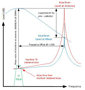
Figure 12 Phase noise at the mixer.
Figure 12 shows this positive effect. The red curve within the picture shows the interferer with its sideband noise. The carrier noise at a frequency offset of 10 percent falls directly into the receive channel and is passed to the IF filter behind the mixer. The green IF filter passband is placed at a position within the spectrum equal to the receive channel at the antenna, because all signals are transferred into the IF filter after the mixer. After the preselector, the level of the red carrier is suppressed while the noise falling into the receive channel is unchanged. This is summarized as follows:
• Relative Phase Noise of the Interferer at Antenna: -180 dBc/Hz at 10 percent
• Total Attenuation of Preselector between the Antenna and Mixer: 60 dB
• Relative Phase Noise of the Interferer at the Mixer Input: -120 dBc/Hz at 10 percent
This simple calculation shows how important the selectivity of the preselector is for overall receiver performance. Any improvement in selectivity by X dB reduces the requirement for all components behind it by the same amount of X dB.
The local oscillator within an IF sampling concept has the same relevance as the sampling clock in a direct sampling concept. The lower the quality of the preselector, the higher the requirements for LO phase noise or sample clock phase noise as well as ADC quality. A local oscillator with poor phase noise will cause a reduction of receiver sensitivity in the presence of interferers even if these interferers have low carrier noise.
For the local oscillator, assume that a phase noise of at least -130 dBc/Hz is needed at the same absolute offset as the interferer at the antenna. The IF frequency is expected to be typically 70 MHz, it is recommended to introduce a slight variation of this IF frequency to avoid negative constellations between input frequency, LO frequency and IF frequency which may lead to spurious signals within the IF. Within the block diagram of the receiver shown in Figure 11 some switchable IF filters are shown that allow not only changes in the IF frequency but also the selection of different bandwidths.
The tuning range of the LO will typically be 70 to 100 MHz. The worst-case situation for the LO phase noise is given when the receiver is tuned to 1.5 MHz where the -130 dBc/Hz phase noise requirement must be met at an offset of 150 kHz (10 percent of 1.5 MHz).
It is recommended to carefully design the LO synthesizer for the lowest phase noise and lowest spurious because this is another key element that drives performance. With a low noise VCO at typical 1 GHz followed by a divider, phase noise of beyond -150 dBc/Hz can be expected for the required LO frequencies. The fine tuning of the LO can be done with a hybrid synthesizer using a combination of a direct digital synthesizer with a phase locked loop.
A level of +17 dBm for the LO signal at the mixer is sufficient with the chosen preselector performance. It must be recognized that with a reduced quality of the preselector, the LO level must go up because the interferer level will go up as well. In parallel, the phase noise quality must also go up.
If an LO synthesizer with a phase noise of -150 dBc/Hz is assumed, then theoretically the selectivity of the preselector can be relaxed from the current 60 dB to 40 dB. This will then lead to an increase of the interferer level after the preselector of +5 dBm which is very high even for high level mixers with +27 dBm LO level. As we strive for the perfect concept for an SDR HF receiver we should, therefore, choose a very low noise synthesizer for the LO signal along with high preselector selectivity.
The Final Data Sheet and Specification of Key Components
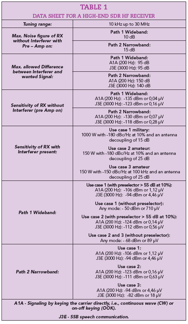
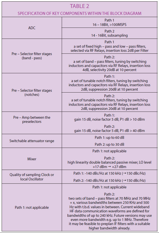
Based on the block diagram shown in Figure 11, the SDR HF receiver will meet the requirement of the data sheet shown in Table 1. This strongly depends on the quality of some key components which are listed in Table 2. The data sheet of the receiver was derived from the following cosite scenario with reference to Figure 9:
For military installations:
- Frequency Offset ΔF: 10 percent
- Total Decoupling: 15 dB
- Interferer Transmit Power: 1000 W
For amateur radio installations e.g. field days:
- Frequency Offset ΔF1 Within the Same Amateur Band: 100 kHz
- Frequency Offset ΔF2 to the Next Amateur Band: > 10 percent
- Total Decoupling: 25 dB
- Interferer Transmit Power: 150 W
Be aware that a high-end receiver will not be able to show its full performance in the presence of low-end transmitters. This fact mandates a feasible value for transmitter sideband noise available for both scenarios. The parameters stated in the following are beyond those of currently fielded transmitters because it is assumed a step ahead in the capabilities for transmitters within the next years as well.
- Excellent Interferer Tx Sideband Noise: -150 dBc/Hz at 100 kHz
- Excellent Interferer Tx Sideband Noise: -180 dBc/Hz at 10 percent
The sideband noise at an offset of 100 kHz is determined by the synthesizer concept within the transmitter while the value at 10 percent can be achieved by using additional so-called cosite filters at the right position within the block diagram. These cosite filters can be switched into the receive chain and then reused as preselector filters in receive mode.
CONCLUSION
Both direct and IF sampling are state-of-the-art concepts for high-end SDR HF receivers. For wideband receivers, direct sampling is the clear choice while for narrowband receivers an IF sampling concept is recommended. For a high-end receiver providing, for example, a panoramic view of the entire HF band while narrowband signals are operated in parallel, it is recommended to use two separate and independent receiver paths representing the two SDR receiver concepts.
The capability of an IF sampling receiver is highly depending on the quality and performance of the preselector between antenna and ADC. With some well-chosen combinations of highpass and lowpass filters plus some notches (composite filters) a high performing and flexible preselector can be built that greatly improves the total capability of an IF sampling receiver. As a rule of thumb, an IF sampling receiver with a good preselector is well usable if other stations are separated by typically 40 dB of antenna decoupling. With lower antenna decoupling, some additional selectivity is required, which can only be added on an intermediate frequency.
OUTLOOK
SDR HF Receivers
Beyond the basic SDR concept of a high-end HF receiver, some optional enhancements can provide more operational benefits for the user. Direct sampling receivers can be realized quite compactly, which allows coupling, for example, of two separate signal paths to build a diversity configuration. With two different antennas including, for example, optionally different polarizations, some interesting capabilities like fading compensation, interferer nulling and others can basically be achieved. These new applications are still at the beginning of their developments, but with cheaper and smaller, but high performing, direct sampling SDR HF receivers, these new capabilities will be the state-of-the-art in the coming years.
SDR HF Transmitters
High-end SDR HF receivers can be designed to tolerate high level interferers while the receiver is still able to provide a high performance. The overall performance of a receiver in the presence of strong interferers is influenced by the quality of these interferers; therefore, it is important that the design of modern transmitters also improves to allow a total improvement of the capability of installations where receivers and transmitters are collocated.
Modern SDR HF transmitters can achieve excellent performance with respect to phase noise if the signal generation uses fully digital mechanisms followed by a well-defined chain of amplifiers and filters. The close in phase noise, e.g. at an offset of 100 kHz, is exclusively determined by those circuits that generate the carrier signals.
In many fielded systems, a low phase noise analog oscillator stabilized by a high quality phase locked loop is the preferred solution. In future transmitters a fully digital solution will provide transmit signals with better phase noise that are also already modulated. The use of digital circuitry will enable a simplified block diagram by eliminating analog mixers and modulators.
Nevertheless, transmitters using analog oscillators are still able to provide excellent performance with respect to phase noise if the details within their design are well chosen. Figure 13 shows the measured phase noise for a high-end transmitter achieving -150 dBc/Hz at 100 kHz offset with a carrier frequency at 14.2 MHz.
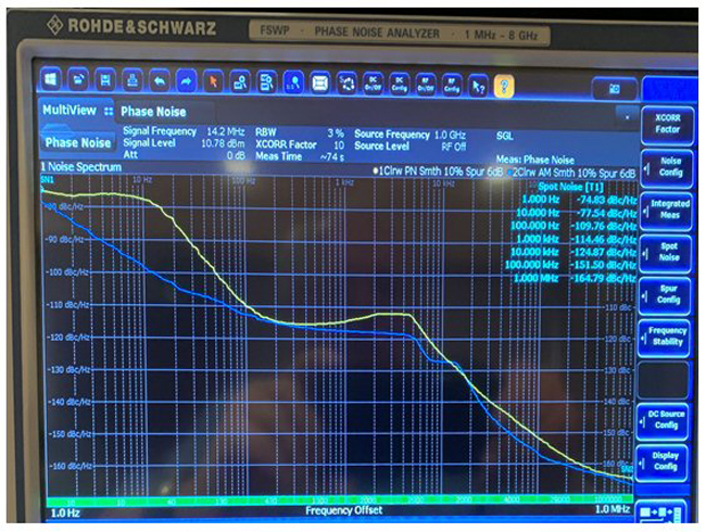
Figure 13 Phase noise of an analog transmitter.
These values are basis for one of the chosen three cosite scenarios earlier in this article. The tested transmitter achieves a phase noise of better than -160 dBc/Hz at 300 kHz, and with some optional filter modules even significantly better values are available.
Beyond the advantages of better phase noise performance in combination with reduced block diagram complexity, digital solutions for transmitters also enable more features like active linearization and advanced power regulation mechanisms that are stable even in the presence of strong backward interferers.
SDR HF Transceivers
Almost all SDR HF receivers and transmitters are part of the same transceiver unit. This allows the reuse of core building blocks for both the receiver and transmitter. These core building blocks are mainly frequency generation and filter functions. The low noise signal generation can provide not only the transmit signal but also the low noise local oscillator for an IF sampling receiver.
In the same way, the receiver’s preselector filters can be switched into the transmit signal chain during the transmit operation to reduce any out-of-band emissions such as noise and discrete spurious. A low transmitter noise floor (lower than -180dBc/Hz used in this article) will be achieved if the preselector appears within the transmit chain at levels of at least +20 dBm. This level corresponds to those for strong interferers in receive mode.
The technical data for some building blocks can and should be harmonized between the data sheets of the transmit and receive modes. This applies in a cosite scenario where two identical transceivers are used as receiver and as interferer. The phase noise at low frequency offsets defines the quality of the interferer transmitter noise, but also the receiver with respect to reciprocal mixing if both paths use the same frequency synthesizer. The same situation applies for the preselector as well, which is inserted at a power level within the transmit chain that is similar to the level of the strongest interferer in the receive mode.
With this strategy the main data for receiver and transmitter parameters can be derived which leads to the best possible system performance, e.g., sensitivity at a given antenna decoupling and frequency offset.
An abridged version of this article appears in the May 2022 print issue of Microwave Journal.
ACKNOWLEDGMENT
We would like to thank Hans Zahnd (HB9CBU), Robert Traeger (Rohde & Schwarz) and Harald Wickenhäuser (DK1OP, Rohde & Schwarz) for their support in the creation of this article.
References
- U. Rohde, J. Whitaker and H. Zahnd, Communications Receivers: Principles and Design, McGraw Hill, Fourth Edition, 2017.
- ARRL, Web: https://www.arrl.org/.