
Editor's Note: The magazine version of this article was condensed in order to fit into the space available for the print edition. This online version is the full article submitted by the authors so is more detailed than the version that appeared in the magazine. We thank the authors for submitting both a condensed and extended version.
Modern HF receivers must fulfill requirements such as sensitivity, robustness and many others. Key requirements often lead directly to RF concepts and architectures with their specific advantages and disadvantages. What would the perfect HF receiver look like today, one that combines all available technologies into the most modern concept of a software-defined receiver (SDR)? Would it employ “IF sampling,” “direct sampling” or something else?
The first very simple HF receiver concepts, as demonstrated by Marconi, were used 120 years ago to enable transatlantic communication. Since then, there have been many improvements by introducing new technologies and architectures step-by-step. Each technological step was founded on the motivation to achieve specific improvements like smaller size or higher sensitivity. In the following, the major steps are summarized:
Step 1: Marconi´s receiver, no amplifiers, no filters but huge antennas.
Motivation for Step1: Demonstrate electromagnetic waves as new media for wireless communications.
Step 2: Vacuum tubes for amplifiers and stable oscillators.
Motivation for Step 2: Improve range and availability of wireless communication equipment.
Step 3: Improvement of involved components, e.g., smaller tubes and better filters.
Motivation for Step 3: Reduce size and weight to allow portable equipment during WWII.
Step 4: Introduction of transistors.
Motivation for step 4: Further reduction of size, weight and power (SWaP) and price to enable mass production.
Step 5: SDR 1st generation introduced.
Motivation for Step 5: Increase the flexibility by replacing fixed hardwired components by software.
Step 6: SDR 2nd generation.
Motivation for Step 6: Further reduce SWaP, tradeoff between performance and flexibility.
Step 7: The perfect HF receiver.
Motivation for Step 7: Best performance with highest flexibility at the same time.
Step 7 is now explored in the following:
The architecture of a receiver is directly driven by some key requirements which must be fulfilled. The number of these requirements can be quite high but for an HF receiver design there are only three major ones: 1) pick up weak and wanted signals, 2) in the presence of strong interferers within a given frequency offset, 3) at the same time.
Within these requirements are hidden values that must be known in detail, for example, the required sensitivity, the maximum level for interferers and the frequency offsets between wanted signals and interferers. These three “golden parameters” can and must be extracted from the operational scenario in which the receiver is used. In combination with the capabilities of typical building blocks, such as analog-to-digital converters (ADCs), these three parameters determine the most suitable receiver architecture.
All further parameters within the data sheet of a receiver based on this architecture are now a direct consequence of the quality of the chosen building blocks e.g., phase noise of oscillators as basis for desensitization.
We will now assess the three golden parameters and design the “perfect architecture” to optimize them. At the beginning we use a general and very simplified block diagram of a digital receiver to identify how the three golden parameters influence the design of major building blocks. The block diagram of any digital receiver can be built by using three major functional blocks: 1) analog preconditioning, 2) ADC and 3) digital signal processing (see Figure 1).
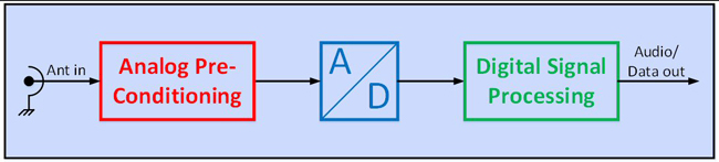
Figure 1 General and simplified SDR architecture.
In the following the three building blocks are described with in more detail:
ANALOG PRECONDITIONING
This block is the coupling element between the antenna input and the input to the ADC. It sets the correct gain and, together with its noise factor, it is responsible for achieving the desired receiver sensitivity. It may, therefore, contain amplifiers and/or attenuators and elements to adapt impedance levels, if required. It may also contain some selectivity to suppress components of the input spectrum that may be problematic for the ADC. These stages are, therefore, the main contributors to defining receiver robustness.
The selectivity between the antenna input and the ADC may be realized either by inserting filters directly on the operating frequency (preselector) or by translating the input signal to an intermediate frequency (IF filter). Receivers that do not use an intermediate frequency are called “direct sampling receivers” while receivers that employ intermediate frequencies are called “IF sampling receivers.” A preselector filter at the operating frequency must be tunable or switchable to cover the desired frequency range of the receiver while the IF filter at an intermediate frequency may be fixed.
The selectivity of a preselector filter may not be sufficient to suppress strong interferers close to the operating frequency of the receiver where weak signals may be processed. In this case, the designer of the receiver is forced to choose an IF concept to achieve the required suppression. The use of an IF frequency allows the use of high selectivity filters, which enables the receiver to pick up weak signals very close to strong interferers.
The use of “direct sampling” or “IF sampling” is, therefore, determined by the use case of the receivers. This means that the question “what is the best receiver concept?” cannot be answered without knowing the spectrum requirements at antenna level. In the following we look a bit closer at the analog preconditioning block for both the “direct sampling” and “IF sampling” concepts.
Analog Preconditioning for Direct Sampling
Direct sampling concepts require a carefully designed gain setting between the antenna input and ADC. This is done by using an amplifier with a well-chosen gain and noise factor to achieve the required receiver sensitivity. Additionally, an adjustable attenuator in front of the amplifier allows the operating range of the complete receiver to be shifted up or down depending on the instantaneous spectrum at the antenna.
A preselector filter, ideally placed directly at the antenna terminal, provides the minimum required selectivity to protect the ADC but also the preamplifier from strong interferers.
Both parts, gain setting and selectivity, shift the input spectrum at the antenna into an operating window at the ADC input defined by the capabilities of the ADC. Figure 2 shows these functional blocks.
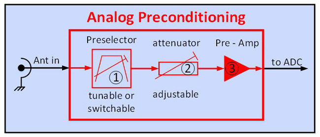
Figure 2 Analog preconditioning for direct sampling.
Analog Preconditioning for IF Sampling
Analog preconditioning for IF sampling adds two more components: 1) an RF synthesizer and 2) an IF filter (see Figure 3).
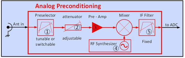
Figure 3 Analog preconditioning for IF sampling.
IF sampling concepts transfer the spectrum of the wanted signal at the antenna to another frequency. There are two main reasons why the IF sampling concept is attractive, despite the higher effort required. One is to insert significantly higher selectivity between the antenna and the ADC, and the other is to achieve higher quality ADC operation, for example, by selecting the right sampling clock for better performance.
An IF sampling concept may be the better choice compared to direct sampling when strong interferers are very close to the wanted frequency. In this case, a preselector filter may not provide sufficient selectivity to suppress the interferers such that the complete spectrum at the input of the ADC is within its operating window.
Transferring the input signal to an intermediate frequency allows the use of highly selective filters with shape factors far beyond the quality achievable by a preselector at the antenna. The price to be paid, however, is that the mixing process may introduce some significant limitation in the spurious performance of the complete receiver. This is because the mixing process, itself, is sensitive to multiple effects, for example, the mixing of all harmonics present at the mixer and others. As a consequence, the ADC may operate within an attractive operating window that allows the best dynamic range for the device; but, the complete receiver may show poor intermodulation performance.
This leads to the fact that the overall performance of an HF receiver concept, either using direct sampling or IF sampling, is always a tradeoff between the performance of the individual building blocks. In other words, an IF sampling concept with high performance analog preconditioning may provide excellent data even when using a poor ADC, and a direct sampling concept using a high performance ADC may not be able to provide good data if the analog preconditioning is insufficient.
What is the Right Concept?
The right concept for an HF SDR always depends on the use case and the quality of the functional blocks that shall or can be used. The quality of the selected building blocks is then very often influenced by associated costs. Consequently, most HF receivers on the market represent a compromise between available technology and feasible costs, but they normally do not represent what is technically possible if costs were not considered.
What is the Perfect Concept?
In the following we will build the perfect state-of -the-art concept for a software-defined HF receiver by combining the best available technology for each of the required building blocks. We will start with an analysis of available ADCs and the performance they can provide.
Reading an ADC Data Sheet
ADC manufacturers are very good in designing their products but they are perfect in designing their data sheets. They promise wonderful data and prove their promises by using ideal settings. These settings may be based on the best relationships between sample rates and the sampled wanted frequencies in combination with well-chosen levels for all involved signals. The given settings within an ADC data sheet may not represent a typical spectral environment for an HF receiver, especially with respect to a high-level multi-signal spectrum.
The receiver designer must be aware of the relevance of important parameters and how they influence each other. Figure 4 shows all major ADC parameters which are important for the design of a high quality SDR HF receiver.
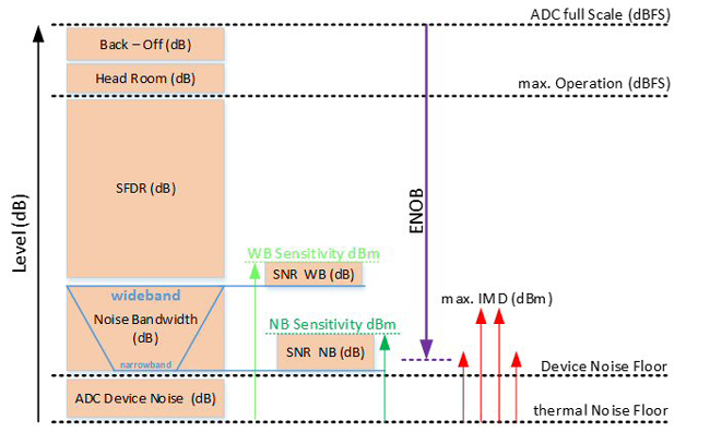
Figure 4 ADC parameters at a glance.
In the end, it is important how large the difference of levels between weak wanted signals and strong unwanted signals is allowed to be at the input of the ADC. This is the most important characteristic in the design of a complete receiver.
The analysis of an ADC data sheet normally starts with resolution, noise factor and other parameters which are linked to achievable sensitivity. We do it here in the opposite direction because it is easier to understand the behavior of an ADC within the complete architecture of a receiver.
We start with the maximum level allowed at the input of an ADC which is the ADC Full Scale Level. The amplitude of the sum of the signals present at the antenna of the receiver must safely remain below this threshold, otherwise further processing steps are strongly affected and will deliver unusable results. If strong signals at the antenna are very close to the wanted frequency, an automatic gain control (AGC) circuitry must set the right maximum gain to avoid overloading the ADC.
The next important parameter is the effective number of bits (ENOB). It indicates how far below the ADC Full Scale Level a weak signal can be found and identified by the ADC. It is important to know that a perfect low-resolution ADC may have a significantly higher ENOB than an imperfect high resolution ADC.
After sampling the input signals, any ADC will show some jitter within the digitized data. Inside this jitter the information of weak signals is hidden and can be extracted, for example, by decimation. Decimation algorithms can be seen as a kind of averaging. Averaging across ten samples, for example, may increase the resolution by a factor of ten while also reducing the sample rate by the same factor. Decimation algorithms basically enhance the effective resolution of the signal processing chain by diving into the noise and jitter at the output of the ADC.
The possible depth of this dive is limited to a point where the jitter of the ADC itself cannot be separated any more from the jitter related to the input spectrum. The jitter from the ADC may also contain jitter from the clock signal; so, it is therefore important that the applied sampling clock is generated with the highest possible quality with respect to phase noise and spurious content.
The value for ENOB does not yet provide any information about the quality of the signal processing chain with respect to intermodulation or any other unwanted signal not present at the input of the ADC but appearing at its output. Unwanted signals at the output of an ADC may be caused by a variety of effects, such as nonlinearity of ADC input stages. These discrete output signals are very often a correlation between sample rates and spectral components of the input signals, but are normally not reliably predictable, either in frequency or levels. Within an ADC data sheet, quality with respect to unwanted signals is given as spurious free dynamic range (SFDR). Values for SFDR are dependent on the settings, especially sample rates, input spectrum and chosen levels at the ADC input.
It is recommended that any ADC be evaluated for a receiver design by applying a typical input spectrum, including the most likely sample rate to measure the worst-case SFDR for this particular use case. This real value may be significantly worse than any promised value taken from the data sheet. This situation makes a direct sampling wideband SDR highly dependent on the quality of the chosen ADC. Any reduction of bandwidth at the input of the ADC, therefore, significantly improves the performance of the whole receiver. The price to be paid is a reduction of the maximum instantaneous bandwidth which can be sampled.
For SDR receiver designed to process the HF band up to 30 MHz while individual signals always remain narrower than some hundred kHz, a good preselector filter is a must. Any additional “dB” of suppression for unwanted interfering signals directly improves the quality of the receiver.
The Best ADC and Its Performance
The ADC is the key component within the concept of an SDR. The dynamic range of an ADC is one of the most important parameters required for the selection of the ADC itself and the receiver concept as well. For very high RF frequencies (far higher than 30 MHz), the possible operating frequencies might be the only available criterion for the selection of an ADC.
For an HF receiver, either a direct sampling capability of any frequency up to 30 MHz, or the capability to process a fixed intermediate frequency typically below 100 MHz within an IF sampling concept is required. The following is a look at the best ADC for direct sampling of signals up to 30 MHz, while also usable within an IF sampling concept with an IF frequency below, but close, to 100 MHz.
Several companies offer ADCs with up to 18-bit resolution using sample rates of up to 100 MHz or more. The input stages can be operated with bandwidths of some hundreds of MHz. This would allow their use with subsampling as part of an IF sampling receiver. Subsampling concepts use a sample rate below the sampled frequencies of interest, which makes the digital output signal ambiguous, not clearly allowing the original input signal to be identified in the frequency domain. Any sampling concept like this requires a clear knowledge about the input spectrum to be sampled; therefore, a sufficient band limitation, such as a bandpass filter is required for subsampling. The combination of a bandpass filter with a subsampling ADC is an important back-end part of an IF sampling receiver concept.
With modern ADC devices an SFDR of 90 to 100 dB can be expected. This means that the maximum allowed difference in levels between a weak wanted signal and a strong interferer can be on the order of 90 dB when both signals are applied at the same time at the input of the ADC.
Starting with the Receiver Architecture
At the antenna level, especially in the HF band, a strong multi-signal spectrum is expected. Unfortunately, the data sheet of an ADC does provide information about its behavior when a multi-carrier interferer with a high total sum amplitude is applied. Consequently, it is mandatory to reduce the bandwidth of the spectrum at the input of the ADC as much as possible.
Separating Narrowband from Wideband
For use cases where, for example, a wideband panoramic spectrum must be monitored, the effective dynamic range may be significantly lower than for monitoring a narrowband communication signal. This implies that the best architecture for receiving wideband signals may, or will, be different than for narrowband signals. This does not necessarily mean that two completely different concepts are required. It means, at least, that the reception of narrowband signals may require completely different settings for hardware gains and filters between the antenna and the ADC compared to the ones required for the reception of wideband signals.
The “perfect receiver concept” can adapt to this situation by first splitting the antenna signal into two different paths, one for narrowband signals and for wideband signals, if wideband and narrowband signals must be monitored fully in parallel. The required signal splitter at the input must be designed for superb intermodulation performance, which leads to a passive device.
The splitting loss should be chosen unequal and should provide less attenuation to the narrowband path while the wideband path may not be critically influenced by a slightly higher insertion loss. Figure 5 shows this first step on the way to the perfect receiver concept.
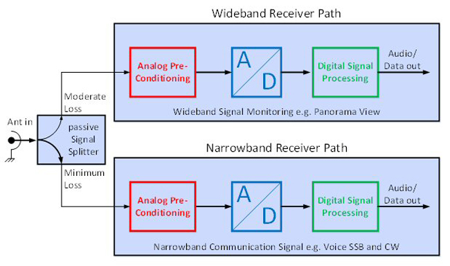
Figure 5 SDR receiver structure.
Both receiver parts may use identical concepts or completely different ones. The minimum difference is at least an individual setting with respect to gain as well as prefiltering between the antenna and ADC to best adapt to the different situations with respect to the spectrum to be processed. The following describes the concept for both receiver paths. The starting point is to analyze the noise situation at the antenna as a basis for defining a suitable sensitivity for the receiver.
Limits to Sensitivity – External Noise
There are two important limits with respect to signal levels at the antenna. One is the maximum level of signals that may occur, and the other is the required, or possible, sensitivity. Both limits influence the capability of a receiver to set an appropriate gain between the antenna and the ADC. The possible, or required sensitivity, is strongly influenced by a noise floor picked up by the antenna and applied to the receiver front-end. This noise floor is variable over time, frequency, location and antenna configuration. As a guideline, the International Telecommunications Union (ITU) has created information provided within ITU-R P.272.