
The setups presented are essentially of two types - thin dielectric sheet testers and z-axis testers. These are the tools that are employed to independently measure the components of the substrate dielectric constant.
It is supposed that suitable propagation models may use this information to better predict propagation mode and effective parameters for design. Other setups, such as bead testers and the Courtney resonator,1 are discussed as they are relevant to the problem of substrate materials evaluation.
Last is the use of free space measurements to obtain in-plane constitutive parameters and may require hardware gating or software time domain gating as provided by the MU-EPSLN™ software package. Appendix A is a summary of these techniques.

Measurement Methods
First among the measurement methods is the class of thin sheet testers which measure the in-plane (x,y) dielectric constant components of  and tan
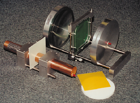
 . They operate upon a portion of an unclad substrate and do not require machining or destruction of the material. Large testers are used at frequencies as low as 0.1 GHz with a sample that is approximately 7 in. across. Smaller testers operate up to 10 GHz and require samples of the order of 2 in. square. The operating band for the coaxial models is a decade and two to three octaves for the rectangular testers. The sample thickness may be as large as 3 mm or so, with the general rule that thinner is better. Sensitivity is not a problem for thin materials, although the first resonance may be weak. Measurements are made at several resonances and, depending upon material thickness, may require correction of the dielectric constant. Corrections are made using reference samples, two thicknesses of the same material and a calibration that combines both of these approaches. Errors in thickness appear quite directly in the value of dielectric constant. Figure 1 shows a coaxial tester which measures an average of the x and y orthogonal components of the sample dielectric constant. The rectangular testers measure both x and y parameters by simple rotation of the sample. The open resonator also fits the category of thin sheet tester.
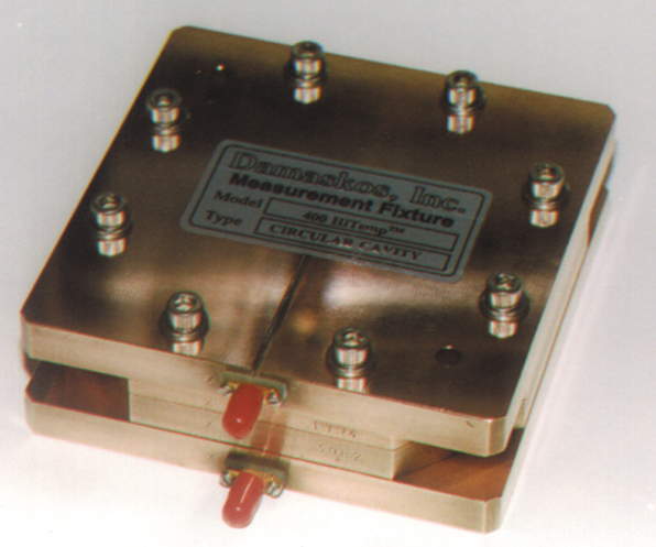
Next is the very important out-of-plane (z) tester, an example of which is shown in Figure 2. For this class of device, the sample must be machined carefully to make intimate contact with the plates of the cylindrical cavity. The operating bandwidth is typically a decade and can be another octave for low loss materials. Often, the same sample can be used in the z-tester and in the open resonator, which facilitates the identification of materials that exhibit anisotropy. Although the height of the cylindrical cavity is kept small to cut off many undesired resonances, laminates must be built up to satisfy the contact requirement. Other related and important aspects of the z-tester are the measurement of resins and polymers that are employed in fabrication of glass laminates, and the measurement of pellets and powdered materials used in molding substrates. This capability offers an element of quality control of such processes. An example of how unsuspected anisotropy may manifest itself is shown in Table 1 . The molding process of the polymer shown produces a very pronounced difference between the components of epsilon in the x,y-directions, 2.45, and in the z-direction, 2.77. The FR4 laminate, too, shows large differences between epsilon in-plane, 4.70, and epsilon out-of-plane, 4.42.

To illustrate the effect of such anisotropy on design, some limits on the effective dielectric constant and impedance of microstrip line as a function of the strip width, W, and the substrate height, d, were calculated using approximate formulas. The results are shown in Table 1. The bounds are determined by first assuming the value of epsilon x,y and air to find the strip parameters and then assuming the value of epsilon z and air. Notable differences may occur which depend on the ratio W/d and require a careful analysis to quantify.
Although the main degree of anisotropy occurs between in-plane (x,y) and out-of-plane (z) components of the dielectric properties, in-plane anisotropy may also occur. Table 2 shows the average data from 2 to 10 GHz obtained with a Model 03 rectangular thin sheet tester for an FR4 laminate at four different in-plane orientations. Although the 1.3 percent difference between the maximum and minimum values may be small, this cavity has ample sensitivity to detect it.

The measurements of Table 3 were made in two bead or pellet testers. The bulk averaged epsilon and loss tangent of the raw material before molding or extrusion may be related to the molded part knowing the density of the pellets and the volume of the sample. This information may assist with control and repeatability of the overall process. The bulk averaged data will be sensitive to pressure on the pellets, although in this example from two cavities, the agreement is very good.

Millimeter-waves
The open resonator is a flexible tool for the purpose of characterizing thin laminates and dielectric sheets and solid materials in the x,y-directions. Operating bandwidths of about two octaves are attained from approximately 10 to 100 GHz, depending on resonator size. Because of high Q and sensitivity, they are capable of measuring the in-plane dielectric properties of very thin materials, substrates and solids. Measurements made with a resonator are non-contacting and permit the sample to be rotated easily, to check for anisotropy. Some data are presented in Appendix B of a 1/8 inch G-10 substrate and a thick disk of beryllia. The rexolite data serve as a rough validation as rexolite is a familiar material.

Ceramic materials such as beryllia and alumina may be measured accurately from the microwave to the millimeter-wave band in a Courtney resonator. Machined cylindrical samples are used to obtain an in-plane average of the parameters, usually at a single frequency. This technique produces the very good values of epsilon in the TE011 mode.
For information about z-direction properties in the millimeter band, the circular cavities discussed earlier may be employed. Where losses are low, measurement of epsilon and loss tangent may extend to V-band (see the circuit board laminate data of Appendix C ). For somewhat lossier materials, the operating bandwidth can sometimes be extended by reducing the diameter of the sample.

Free space measurements are a non-cavity way to determine the x,y-direction properties of laminate and substrate materials in the millimeter band. Reasonably small samples suffice because of the short wavelengths. A setup that is designed for use from approximately 18 to 65 GHz is shown in Figure 3 . In a W-band free space setup, measurements of the in-plane epsilon and loss tangent of an FR4 laminate were made with results that are presented in Table 4 . To make the measurement, software gating was employed to reduce the effects of multipath. The measurements were quite noisy, but nonetheless reduceable as the frequency averaged values and standard deviations of the parameters show. The implicit assumption is that the material properties are not frequency dependent over this band. Validity of the measurement is suggested by the quality of the rexolite data.

Conclusion
Alternative means of determining the dielectric constant and loss tangent of substrate materials are presented. These are mainly cavity-based methods. They result in constitutive parameters in- and out-of-plane of the substrate that give adequate results in the microwave and millimeter-wave bands. They may be used to model the effective characteristic impedance and propagation constant and to explore the importance of substrate anisotropy upon these geometry dependent parameters.
References
1. W.E. Courtney, "Analysis and Evaluation of a Method of Measuring the Complex Permitivity and Permeability of Microwave Insulators," IEEE MTT Transactions , Vol. 18, No. 8. August 1970, pp. 476-485.
2. "IPC-TM-650 Test Methods Manual," Institute for Interconnecting and Packaging Electronic Circuits, Lincolnwood, IL.
3. "ASTM 2520, Standard Test Methods for Complex Permittivity of Solid Electrical Insulating Materials at Microwave Frequencies and Temperature," American Society for Testing and Materials, West Conshohocken, PA.
4. D.W. Pozar, Microwave Engineering , Addison Wesley, 1990.
5. "Damaskos Inc. Material Measurement Systems - 2003 Catalog," Damaskos Inc., Chadds Ford, PA.
 Nickander J. Damaskos received his BS degree in mathematics from CUNY, his MS degree in electrical engineering from Wichita State University and his PhD degree in electrical engineering from Carnegie Mellon University in 1956, 1961 and 1963, respectively. He is currently president of Damaskos Inc. and program manager of R&D projects in microwave measurements of materials and RCS design.
 Benuel J. Kelsall received his BS degree in chemistry from West Chester University and his PhD degree in physical chemistry from Case Western Reserve University in 1975 and 1980, respectively. He is vice president of Damaskos Inc.