
The data rate evolution necessary to meet new mobile telecommunication standards (9.6 kb/s for GSM, 115.2 kb/s for GPRS, 384 kb/s for EDGE and 2 Mb/s for UMTS) demands the use of wider bandwidth and bandwidth-efficient linear modulation techniques. Therefore, telecommunication manufacturers require improved specifications for 3G standards. In particular, lower third-order intermodulation products and higher RF power handling capabilities, together with a low insertion loss, are required for all components of the base station transmit chain and specifically for isolators and circulators. Consequently, the new Temex product line of isolators and circulators has been developed to meet the requirements of UMTS standards.
UMTS Requirements
Standard circulators and isolators for GSM base station applications are designed to sustain RF power up to 100 W CW (where CW stands for continuous wave) with intermodulation distortion (IMD) in the range of -65 to -75 dBc. Higher data rates require the use of linear modulation techniques with strong time-varying RF envelopes. That is because nonlinear transmitters cause the varying amplitude information to spread onto adjacent channels. Therefore, to minimize this effect, very linear components must be used on the transmit chain. Power amplifiers are the most critical components, although all components contribute to the overall nonlinearity. The requirement, then, is for isolators and circulators with a high level of linearity, typically with IMD in the order of -80 to -90 dBc, with two-tone test input power at +44.5 dBm each, together with a low insertion loss.
Design and Test
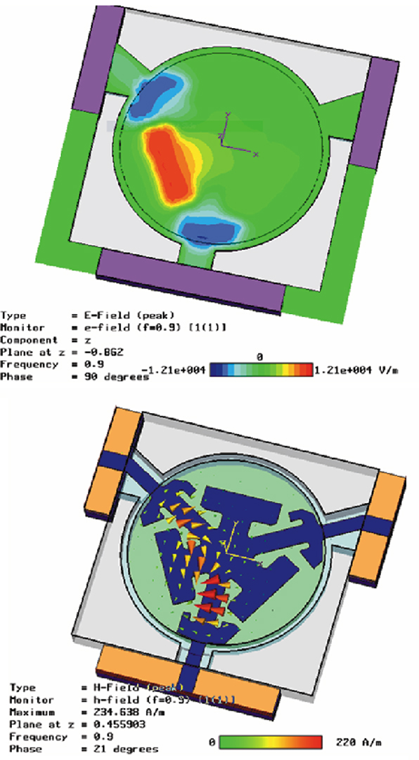
To meet these criteria the new drop-in isolators and circulators are constructed with a center conductor (stripline) sandwiched between two ferrite disks. These ferrites are then placed between ground planes and magnetically biased by permanent magnets outside the ground planes. The design has been developed using 3D electromagnetic software (time domain). The size, type and geometrical structure of the critical component (that is, magnet, ferrite and stripline) have been optimized using this software. The electrical and magnetic field distribution of a drop-in structure is shown in Figure 1 . In the development process, simulations were used, together with microwave measurements, to optimize small-signal parameters and third-order intermodulation products.

A specific test configuration used to measure the third-order intermodulation product is shown in Figure 2 . Here, the two test carriers are amplified in PA1 and PA2, and are then summed in the filter combiner. Intermodulation products are generated by the device under test (DUT) and pass through the diplexer. The Tx port of the diplexer is connected to a 50 to 100 m reel of low level cable, terminated with a low power termination. Most of the power is lost in the cable and most of the intermodulation products generated by the termination are dissipated in the return path through the cable. Also, the transmit signal on the Rx port is filtered to reject CW test tones and to select one of the two intermodulation tones. The difference in amplitude between the CW test tone and the intermodulation tone is measured using a spectrum analyzer.
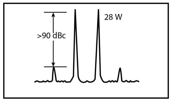
The result is that the free spurious dynamic range without the DUT is better than -120 dBc, with two test tones at +44.5 dBm (28 W) each. Also, ultra low intermodulation values have been measured at levels below -90 dBc, with two test tones at 28 W each (see Figure 3 ). Standard models have been measured at levels below -70 dBc under the same input power conditions.
Electrical Characteristics
The circulators and isolators operate at frequencies ranging from 2080 to 2200 MHz. This interval covers the full bandwidth allocated for UMTS communications. The standard operating temperature range is specified as -10° to +85°C. However, this range may be extended or shifted according to the specific application requirements.
The new line of circulators includes five basic models. The common features are lead-free design (loads, attenuators and striplines are soldered with Sn96Ag4 solder paste) and BeO-free (chip terminations are in AlN and Al2O3).
One model (NE1101-300) is intended for low power applications where the reverse power does not exceed 1 W, and the others are high power devices capable of handling up to 200 W of forward CW power and 100 W of reverse CW power. The device package size is 19.05 x 19.05 mm. Models NE1101-100 and NE1101-200 are drop-in isolators with high power and low intermodulation product capabilities. Terminations for these devices are load, 20 dB attenuator and 30 dB attenuator. For reverse power detection purposes, the terminations can be equipped with a pin tab at the center position for the attenuator and at the left or the right for the load. The package size for these devices is 19.05 x 25.4 mm.

Models NE3101-100 and NE3101-200 are circulators. One is a standard drop-in package (19.05 x 19.05 mm) and the other an SMD package (19.05 mm in diameter), as shown in Figure 4 . An insertion loss better than 0.25 dB can be achieved in the useful UMTS bandwidth (2.110 to 2.170 GHz) for all the models. Typical small-signal parameter measurements are shown in Figure 5 and performance data for various models is presented in Table 1 .
| Table 1: Performance Data* | |||||
| NE1101-100 | NE1101-200 | NE1101-300 | NE3101-100 | NE3101-200 | |
| Frequency** | 2080 to 2200 | 2080 to 2200 | 2110 to 2170 | 2080 to 2200 | 2080 to 2200 |
| Isolation (dB) | >21 | >21 | >23 | >21 | >21 |
| Insertion loss (dB) | <0.3 | <0.3 | <0.3 | <0.3 | <0.3 |
| VSWR | 1.20 | 1.20 | 1.15 | 1.20 | 1.20 |
| CW power (W) |
|
|
|
|
|
| IMD*** (dBc) | <-85 | <-85 | <-70 | <-70 | <-85 |
| Features | low IMD, load | low IMD, attenuator | low power isolator | circulator | SMD circulator |
| *In the temperature range -10° to +85°C | |||||

Conclusion
This article has presented the specific features and technical characteristics of a series of isolators and circulators for UMTS (3G) applications. By using new simulation models on 3D electromagnetic software, high power, low intermodulation and low insertion loss devices have been designed. The result is a new range of circulators and isolators that covers the majority of telecom supplier requirements for 3G applications.
Temex, Paris, France, +33 1 69 82 20 00, info@temex.fr, www.temex.net. Circle No. 300