
Ferrite switching networks have a wide variety of uses in commercial and military, space and terrestrial, and low and high power applications. These include low noise amplifier (LNA) redundancy switches, T/R modules, high power isolators and switch matrices. Ferrite switches are desirable for these applications due to their high reliability and low loss, and because they contain no moving parts or thermal noise sources.

Ferrite latching switches are functionally equivalent to conventional (fixed-bias) circulators, but with a selectable direction of circulation. RF energy can be routed with low insertion loss to either of two outputs, depending on the polarity of the control pulse. Hot switching is possible, as the ferrite switch will not be damaged by applied power during a switching event, which is on the order of 1 ms. Once the control pulse is sent to the switch, it is latched to the selected state indefinitely, without the need for further commands or applied power. A switching isolator is similar to a circulator, but one of the two output ports is terminated in a matched load.

Because multiple circulators and isolators are combined to form switching networks, the overall size, mass and insertion loss can quickly escalate. A new family of ferrite switch products addresses these critical performance areas by utilizing a patent-pending technique to minimize the size of the internal transitions within networks. This technique provides for designs with a better than 50 percent reduction in size and mass.
Triad Switch Network
For applications such as LNA redundancy switches, triad switch networks are generally used instead of a single switch junction. To form a triad, two switching isolators are added to the outputs of a single switch junction, resulting in the block diagram shown in Figure 1 . The triad configuration provides for stability in return loss, insertion loss and isolation regardless of the impedance match at the output port.

Using traditional design techniques, the disadvantages of using a triad switch are the additional loss, size and mass of the two output isolators.
However, through the use of a new technique for reducing the size of the ferrite network, the size of the triad switch is made comparable to that of a traditional single switch design for WR-28 waveguide, as shown in Figure 2 . The WR-28 miniaturized triad switch is 0.85" tall by 1.19" wide by 0.82" long, and the two output ports are located on the face opposite to the input port. The small size and port configuration make the miniaturized triad switch ideal for applications such as a dual redundant LNA assembly that is mounted directly behind an antenna array.
The insertion loss of the miniaturized ferrite triad switch also compares favorably to traditional switch products. Figure 3 shows the loss of the miniaturized triad switch is nearly half that of the traditional triad switch over the operating band of 29.5 to 30 GHz. The key performance specifications of the miniaturized triad switch are summarized in Table 1 .

|
Table 1 | ||
|
Parameter |
Specifications |
Typical Value |
|
Frequency range (GHz) |
0.500 at Ka-band |
29.5 to 30.0 |
|
Insertion loss (dB) |
<0.2 |
0.15 |
|
Isolation (dB) |
>35 |
40 |
|
Input return loss (dB) |
>23 |
25 |
|
Output return loss (dB) |
>23 |
25 |
|
Temperature range (°C) |
5 to 70 |
0 to 75 |
|
Mass (grams) |
<21 |
19 |
Switch Network
The triad switches can be combined into larger assemblies, such as a 1:4 switch, for further multiplexing. By utilizing triad switches, high isolation is preserved from the ON path to the three OFF paths. A block diagram of this 1:4 switch network is shown in Figure 4 .
This network can be constructed using three of the miniaturized triad switches discussed in the previous section, but further size efficiencies are attained by optimizing the transitions between the three triad switches.
The result is the 1:4 switch network shown in Figure 5 . In WR-28 waveguide, this switch network has outline dimensions of 2.0" by 2.4" by 0.4" and a mass of less than 50 grams.
Ferrite C/R Switches
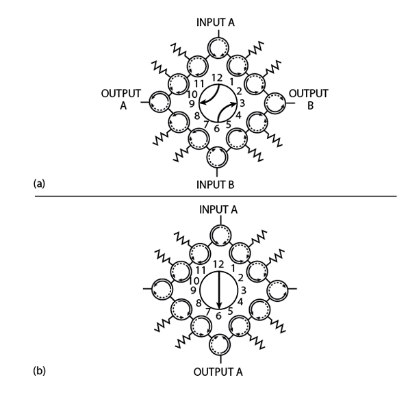
The same process used to reduce the size of the triad switch networks has been applied to a product that is a ferrite switch equivalent to a mechanical "C" or "R" (transfer) switch. The ferrite C/R switch is configured as a ring of 12 ferrite switches, so the switching is performed electronically with no moving parts. This results in a highly reliable product that can be hot switched at high repetition rates as often as desired during integration, test and flight.
Eight of the 12 switches are terminated with loads to provide isolation between any combinations of the four input/output ports (see Figure 6 ). In addition to isolating the OFF ports from the ON ports, this configuration provides built-in reverse isolation of better than 70 dB to protect the input ports from reflections at the outputs. The typical insertion loss is 0.3 dB in the C switch configuration.
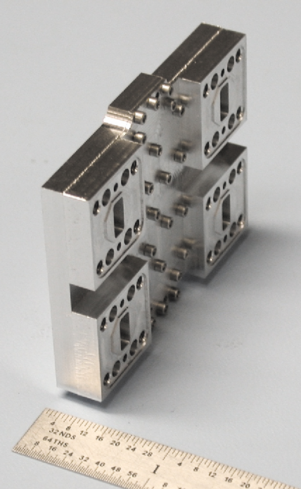
Using the traditional design techniques, a ferrite switch network of this complexity would be quite large, but this miniaturized WR-28 switch network is approximately the same size as a WR-28 mechanical switch, with a base of 1.75" by 1.75" and a height of 0.75". The size reduction of this product over traditional ferrite switches is illustrated in Figure 7 , where the miniaturized ferrite C/R switch is pictured next to the equivalent quantity of traditional ferrite switch components (12 switches and eight loads).

Conclusion
A new ferrite switch design technique has yielded a family of miniaturized, low loss switch networks, ready for integration into the smaller and lighter systems of today. Although these products have been shown for Ka-band operation, the same patent-pending design techniques can be applied to other frequency bands and switch networks to create custom configurations.
EMS Technologies Inc. , Space and Technology Atlanta, Norcross, GA (770) 263-9200 ext. 4200, www.ems-t.com, Circle No. 302