
Two new designs of a microstrip Wilkinson power divider feature stub structures for miniaturization. The dividers operate at 2.5 GHz and only occupy a 15.6 × 17.6 mm area. Results show good agreement between measurements and simulation, demonstrating improved performance relative to the classic design.
The field of microwaves has grown considerably over the past several years, with many telecommunications applications. This has enabled new technologies for the realization of more compact hardware with improved performance at higher operating frequencies. Waveguide transmission lines at mmWave frequencies, traditionally chosen for low dissipation losses and electrical performance, have more recently been replaced by planar structures for many applications.1-3 Planar structures have proven to be practical because it is possible to add active or passive components on their surfaces, with the integration of passive components into the circuit a major goal for the miniaturization of future devices and systems.
Microstrip and stripline transmission lines have desirable properties, such as low cost, light weight, small and compact size, compatibility with integrated circuits, better reliability and good reproducibility.3,4 The most common is microstrip,4,5 which comprises a dielectric substrate completely metallized on one of its faces (i.e., the ground plane) and a metal strip on the other face.
The power combiner/divider is an essential element in the design of mixers and power amplifiers. Used as a divider, its role is to divide a signal at its input into several identical signals at its output. As a combiner, it adds the power of several inputs at a common output. The power divider is reciprocal, a passive component with at least three ports: an input and two or more output ports. The output ports can be isolated, or not.4
The main advantages of a planar power divider are ease of integration with other technologies and the ability to withstand relatively high power levels. The planar nature of its construction supports bulk processing, enabling inherently low manufacturing costs. It exhibits good port-to-port isolation with moderate losses. One disadvantage is a quarter-wavelength (λ/4) transmission line is normally required in the design.
The most popular power divider/combiner structure is the Wilkinson (see Figure 1).4 It is composed of an input port matched to a characteristic impedance Z0, two λ/4 lines of characteristic impedance Z=√2Z0 and two outputs matched to Z0. A resistance R=2Z0 is connected between the two output ports to handle an output power imbalance.5 Different techniques have been described over the years to reduce the size of the classic Wilkinson architecture, including the use of planar artificial transmission lines,6 defected ground structures,7 fractal structures,8 capacitive loading,9 lumped elements10 and stubs.11-13 In this work, new power divider designs using stubs are introduced to reduce the size of the classic Wilkinson structure.
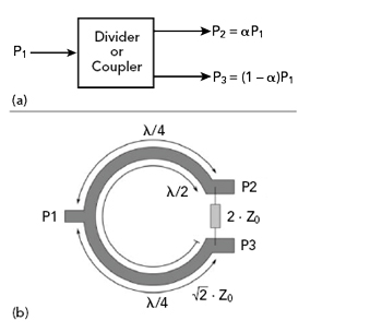
Figure 1 Power divider signal flow (a) and Wilkinson layout (b).
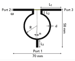
Figure 2 Classic Wilkinson power divider layout.
MICROSTRIP POWER DIVIDER DESIGN
The classic Wilkinson power divider is a single microstrip line on a dielectric substrate (see Figure 2). The proposed microstrip power divider with stubs is shown in Figure 3.
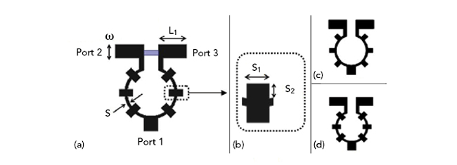
Figure 3 Microstrip power divider with stubs (a), stub unit cell (b), power divider with open-ended stubs (c) and power divider with cross-ended stubs (d).
Several parameters characterize the microstrip transmission line and power divider performance. Assuming a quasi-TEM mode of propagation,14 the phase velocity in microstrip is given by:

where c is the speed of light and εeff is the effective relative permittivity, which is typically 2.9 for microstrip lines.15 The characteristic impedance of the transmission line, Z0, is given by:14

for W ⁄ h ≥ 1, where W is width of the conducting line (see Figure 3), and h is the height of dielectric substrate.