
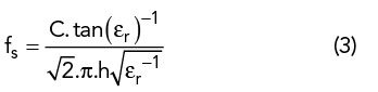
In microstrip, only the dominant (i.e., quasi-TEM) mode propagates. Surface waves are undesirable, as they couple with the quasi-TEM mode. They become significant only at the frequency fs, where:2
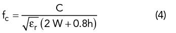
Higher-order mode excitation is avoided by operating at a frequency lower than the cutoff frequency of the first higher-order mode, which is given by:16
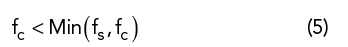
In practice, the operating frequency of a microstrip line is given by:14
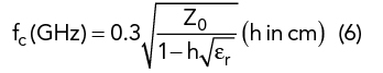
and is calculated by:
FINAL DESIGN PARAMETERS AND SIMULATION
Figure 3 shows the planar design of the prototype dividers. It is a half tri-plate circulator structure17 with planar input/output ports. One of the objectives of this work is to achieve a characteristic impedance at the input/output ports close to 50 Ω. The width W of the input/output lines according to the coupling angle and the center circle radius are as follows:
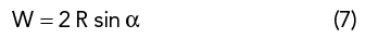
The width of the input/output port lines are adjusted to W = 3 mm to achieve a characteristic impedance of 50 Ω. The parameters in Table 1 are optimized using Ansoft HFSS, and the simulation results of the two power divider designs are shown in Figure 4.
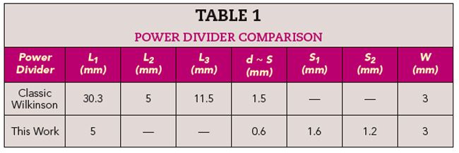
The prototype power dividers are easy to fabricate; and they occupy areas of only 15.6 × 18.8 mm and 15.6 × 17.6 mm, respectively, which is about a 93 percent size reduction compared with the classic Wilkinson power divider.
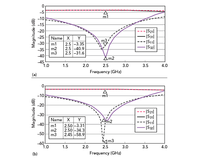
Figure 4 Simulated power divider frequency responses with open-ended (a) and cross-ended (b) stubs.
EXPERIMENTAL RESULTS
The prototype powers dividers were fabricated on an FR4 substrate (εr = 4.5, h = 1.6 mm). Figure 5 shows the fabricated prototypes alongside a conventional Wilkinson power divider. A surface mount resistor was placed between the two output ports for improved isolation. A Keysight E5071C network analyzer was used for the measurements, and Figures 6–9 compare the measured and simulated performance, which are in good agreement. Little difference was observed in the measured performance of the two prototypes. At the operating frequencies, |S21| and |S31| were around -3.4 dB for both. |S11| was -25.75 dB for the divider with the open stubs and -27.64 dB for the divider with cross stubs. Coupling between the output ports, |S23|, was -26.35 dB for the divider with open stubs and -28.25 dB for the divider with cross stubs. Figure 10 shows the measured phase difference between the prototype dividers’ output ports. The output phase difference over the operational frequency range of 2.5 GHz is 0 degrees.
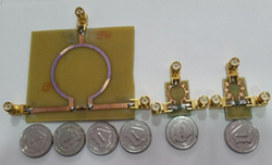
Figure 5 Classic Wilkinson power divider (left) vs. 2.5 GHz stub-loaded power dividers (right).
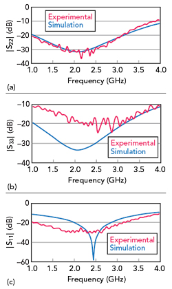
Figure 6 Measured vs. simulated reflection performance of the prototype open-stub power divider: |S22| (a), |S33| (b) and |S11| (c).
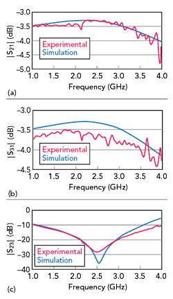
Figure 7 Measured vs. simulated transmission performance of the prototype open-stub power divider: |S21| (a), |S31| (b) and |S23| (c).
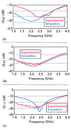
Figure 8 Measured vs. simulated reflection performance of the prototype cross-stub power divider: |S33| (a), |S22| (b) and |S11| (c).
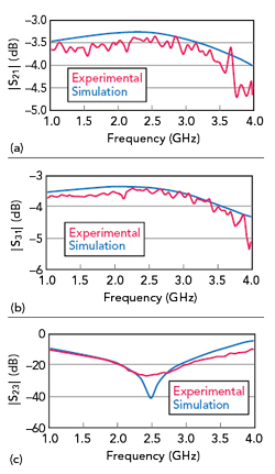
Figure 9 Measured vs. simulated transmission performance of the prototype cross-stub power divider: |S21| (a), |S31| (b) and |S23| (c).
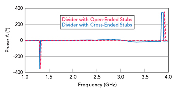
Figure 10 Phase difference between the port 2 and 3 outputs for the prototype power dividers.