
Fabricating a high performance 2 x 16 transmit/receive (T/R) switch to feed a millimeter-wave Rotman or Lunenburg lens antenna array has in the past been a complex and space-consuming configuration. A new T/R switch assembly has been designed that features a compact, unique package containing a 2 x 16 transceiver switch matrix and low noise amplifier (LNA) front-end for a custom wireless application.

The model AY-G20S-1 assembly is a PIN diode activated switch that connects a transmitter to any of 16 ports and rapidly switches from transmit to receive mode while maintaining high isolation between the transmitter and receiver without degrading receiver performance. The unit operates at 28 GHz with a 1 GHz bandwidth with WR-28 waveguide ports for the transmit input and receive output. The 16 waveguide input/output ports are on an arc to feed or receive signals from a Rotman or Lunenberg lens. Figure 1 shows the assembly's mechanical outline.
The 16 waveguide outputs provide narrow 8°, 3 dB beam widths during transmit mode. During receive mode, the lens directs the signal to one of the 16 waveguide ports, depending on the direction of the received wave front. As seen in the block diagram shown in Figure 2 , the transmit signal passes through two single-pole, four-throw (SP4T) switches to arrive at the waveguide outputs with a typical loss of 7 dB. In the receive mode, the signal passes through a SP4T switch, through an LNA with 14 dB of gain and then through a second SP4T switch to the receive waveguide output. The receiver path noise is less than 7 dB with an overall typical gain of more than 7 dB. Table 1 lists the AY-G20S-1 T/R switch assembly's key performance specifications.
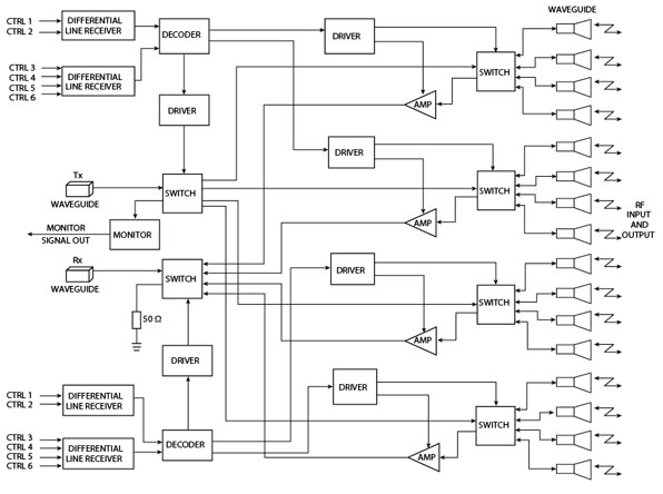
The switch assembly's paths and modes are controlled by two six-bit digital words delivered to balanced line drivers. The line drivers feed decoders that provide TTL control signals for the SP4T switch drivers and LNA bias.
The topology utilized in the AY-G20S-1 is a Ka-band waveguide feeding waveguide-to-coax transitions and coaxial transitions to low loss Teflon" microstrip. The Teflon board is epoxied to an FR-4 board that carries the DC and control signals to the switches and LNAs. The switches are GaAs monolithic chips using high speed shunt PIN diodes. Each switch provides 30 dB of isolation. The LNAs are also GaAs monolithic chips containing a two-stage FET amplifier. During transmit mode the LNAs are turned off by the PIN diode driver that provides a -1.5 V control voltage to the FET gates. The isolation between the transmit and receive lines is greater than 60 dB with a maximum average transmit power of 1 W. A lumped element high pass filter provides isolation between the SP4T switch and the LNA. The SP4T switch video transient, feed through voltage at the LNA gates is thereby reduced to a safe level so as not to interfere with the LNA on/off function.
|
Table 1 | |
|
Frequency (GHz) |
27.5 to 28.5 |
|
Input/Output |
WR 28 |
|
Transmit insertion loss (dB) |
7 |
|
Receive path gain (dB) |
6 |
|
Switching speed (ns) |
20 |
|
RF power (dBm) |
33 |
|
Output power monitor |
yes |
|
Isolation (dB) (min.) |
60 |
Conclusion
A new custom-designed 2 x 16 antenna T/R switch matrix assembly has been described that offers a compact high performance configuration for 28 GHz wireless applications. The new T/R switch is ideal for today's low cost, compact communications systems. Additional information may be obtained from the company's Web site or by contacting a sales representative directly.
MCE/KDI Integrated Products, Whippany, NJ (973) 887-8100, www.kditriangle.com.
Circle No. 303