
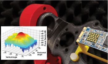
Figure 1 mmWave phased array beamforming measurement.
Since 2005, from the time we first began working on mmWave IC designs for consumer electronics, we have witnessed first-hand the fast-paced development and growth of a multitude of new mmWave solutions addressing three main market pulls: automotive radar (77 to 81 GHz), 60 GHz unlicensed applications and, of course, 5G at 28, 39 and 44 GHz. These applications, due to the nature of mmWave propagation, rely heavily on the quality of the system’s mmWave phased array beamforming capabilities at the algorithm, circuit and antenna levels. The days when antenna designers could characterize and fine-tune their designs independently from the other parts of the system are long gone. Optimizing the performance of these complex systems requires many iterative measurements and careful codesign among engineers of varying disciplines. Further, integrated antennas in the module necessitate over-the-air (OTA) measurements to characterize the system (see Figure 1).
Phased array antenna performance relies on beamforming technology. Optimizing the beamforming performance requires multiple disciplines, which extend beyond the antenna design: beamforming has critical ramifications in the RFIC design and the algorithm to control it. Thus, testing the mmWave phased array and beamforming involves multiple experts - from the algorithm software to baseband to RF to the phased array antenna - who will compete for access to the test system to adjust their designs. Some of the tests may take hundreds of hours to complete; switching among different setups will be even more time consuming. With this shift in complexity, using traditional anechoic chambers for mmWave OTA testing is far from ideal because of their size, cost and accessibility.
MULTIPLE CHAMBERS
Having to share one big chamber is not practical and slows development. Instead, it is more efficient to have multiple, compact mmWave chambers, enabling OTA measurements to proceed in parallel, rather than sequentially. Through many years of developing and testing mmWave ICs, we have learned that starting with one chamber is necessary, yet rarely enough for a successful project. As a rule of thumb, even with a large chamber on site, adding two or three mini-chambers is recommended.
FORM FACTOR
Two primary factors determine the best size for the radiation pattern test chamber. First, the chamber must be large enough for the measurement to be in the far field. Second, the distance between the transmitter and receiver should be as small as possible to minimize cable loss and path loss.
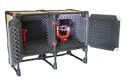
Figure 2 The MilliBox MBX02 anechoic chamber has a 77 cm far-field distance and measures 4 x 3 x 2 ft.
At RF/microwave frequencies, the anechoic chamber is typically a room that is 3, 5 or 10 m on a side. These are bulky and expensive to install, and they are much larger than the far field of most mmWave systems. For example, the far field of a 6 cm array at 28 GHz is about 70 cm distance from the source, making a traditional microwave chamber clearly overkill. With lab space limited, it is likely not possible to install one or more walk-in chambers.
Small chambers are desirable because they help resolve these two issues: cable length and the number of chambers that can be fit in a lab. As cable losses are not negligible at mmWave bands, shorter cables give the best signal integrity. Also, as already noted, having multiple chambers in a lab maximizes design efficiency. As it turns out, a compact, lab bench chamber is large enough to meet the far-field requirements for mmWave testing and small enough for several to fit in a single lab.
After years of experimentation, we determined that 4 × 3 × 2 ft. is the most versatile chamber size for the majority of mmWave applications (see Figure 2), although higher gain antennas may require a longer far-field distance. With a modular chamber design, cubic sections can be added to extend the far field beyond 2 m. Providing instrument bays directly below the chamber enables the measuring instruments to be connected below the device under test (DUT) and probe antenna, which minimizes the cable lengths and loss.
FRAME CONSTRUCTION
For many years, the typical RF anechoic chamber was made as a big metal box lined with microwave absorber and ferrite material, some as a copper mesh Faraday cage. Perhaps surprisingly, these do not work well for mmWave measurements. At mmWave frequencies, metal is not beneficial when testing high gain phased arrays. From our experience making mmWave OTA measurements, we have gradually eliminated metal from the test chamber. Compared to metal, a chamber made almost entirely of wood and plastic helps reduce stray reflections. We have observed that the accuracy of the measurement is influenced more by multipath inside the box rather than noise and interference from outside. Our mmWave antenna test systems have less than 1 percent metal (e.g., motors and wires).
To further eliminate reflections and achieve the best performance, the inside of the chamber should be padded with 4 in. thick mmWave corrugated absorber, heavily loaded with carbon. The mmWave absorber provides about 50 dB attenuation from 18 to 95 GHz, enough to confine the signal inside and attenuate interference from nearby chambers or setups.
COST
An important consideration when choosing a test chamber is price because everybody has a limited budget for test equipment. As one chamber is not enough, if the entire budget is allocated to it, the development effort will be throttled as engineers line up trying to use it. A traditional mmWave test chamber costs $200,000+, a major investment making it difficult to justify buying more than one. To get more chambers, R&D teams may resort to do-it-yourself (DIY) measurement setups, built from materials obtained at the local hardware store and motors and absorbers purchased online. While the material cost is low, the trade-off is that performance and reliability are unpredictable. Above all, the DIY effort diverts engineering from product development and associated testing. While building a one-off test chamber may be okay, it is hard to scale this to building more than one.
CABLE LOSS AND WIRING
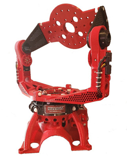
Figure 3 GIM03 mmWave 3D antenna positioner, designed for cable routing.
The cabling from the instruments to the DUT must be carefully considered during the design stage, especially for mmWave measurements, to avoid two main issues when wiring an anechoic chamber and 3D positioner for mmWave phased array applications.
The first issue is related to the chamber size: if the chamber is too big, cable length and the resulting loss are prohibitive. To minimize the loss, the instruments may be placed inside the chamber. However, this can cause reflections or generate interference, degrading the measurement. With more compact chambers, the instruments are placed outside, and the wiring is routed through the walls, traditionally accomplished using a panel of bulkhead connectors. However, these connectors are lossy and constrain the type and number of connections to the DUT. Our approach is to simply place an 8 cm diameter hole in the chamber floor below the 3D positioner and the horn post, which enables routing with direct connections to the instrument bay below the chamber. This does not limit cabling options.
The second issue relates to moving the DUT on the 3D positioner. Most 3D positioners and turntables are simple mechanical fixtures focused on the motion and position of the DUT. Rarely do they optimize the cable routing to and from the DUT, which often leads to tangled cables. The common solution using rotary joints or slip rings may not be practical for the mmWave signals or the DUT control lines using USB or ribbon cables. We designed mmWave 3D antenna positioners to accommodate cable routing: the centers of all rotation axes are hollow, so the cables can be fed through, with less stress during DUT motion (see Figure 3). The importance of cable routing should not be underestimated when choosing an OTA measurement setup.
HARDWARE/SOFTWARE FLEXIBILITY
Through the years working on mmWave designs, we know that plans change and needs evolve. When OTA measurement solutions are either too custom or too standard, the lack of flexibility can limit the utility of the system. The best solution is usually between the two ends of the spectrum.
Many mmWave test chambers come bundled as a complete solution with the hardware and software fully integrated. The software provided by the vendor has a set of pre-defined measurements fully implemented. This is an advantage as a turnkey solution, where the software is optimized to control the test equipment using pre-determined test parameters and the user does not want to invest in software development. However, it is a disadvantage if the desired features are not available, a company prefers to use its existing equipment or the engineers want the freedom to choose the equipment and test methodology for the DUT, rather than the equipment vendor determining how it should be tested.
MODULAR, FLEXIBLE ALTERNATIVE
From our experience developing mmWave ICs and facing these test and measurement trade-offs, we developed a modular anechoic chamber, called MilliBox, which we designed to provide a flexible solution to support multiple scenarios (see Figure 2). The frame of the MilliBox test chamber is modular, so sections can be added to increase the far-field distance beyond the 77 cm baseline, if required. Since DUTs have different sizes and weights, we developed three standard 3D mmWave antenna positioners, all software compatible (see Figure 3).
MilliBox is not tied to any instrument vendor. A Python software platform provides the capability to control the mmWave 3D positioner and measurement instruments. The source code includes a virtual instrument software architecture interface and fully implemented example using a spectrum analyzer or vector network analyzer setup. While the specific commands will vary among instrument suppliers, the platform makes it straightforward to write commands for any set of instruments. Python is free, runs on any operating system and is the most popular language for test automation. One key advantage of this software framework is it can easily be extended by the user, meaning the control of the DUT and any instrument can be integrated into a single framework. For example, capturing or setting the phase vectors from the DUT during the sweep can provide insight into system performance.
SUMMARY
Engineers developing mmWave systems and needing to make OTA measurements have several options when choosing which type of anechoic chamber will best meet their needs (see Table 1). For generations, traditional microwave anechoic chambers have been the go-to solution for antenna radiation pattern measurements. Searching for solutions to fill our own OTA testing needs, we found the traditional chamber and other existing options were not scalable due to their cost, size and engineering effort. For us, the most important requirement was scalability to support a team of engineers needing frequent access to OTA measurements to optimize beamforming performance.

Our search led to the development of MilliBox, which was designed to be compact, affordable and flexible - bridging the gap between traditional mmWave chambers and DIY solutions. The accuracy and repeatability of a MilliBox are better than a DIY solution. The price is an order-of-magnitude lower than the typical mmWave chamber and competitive with a DIY solution, factoring in the engineering required to design and build the DIY chamber.