
The measurement community has a substantial and increasing interest in utilizing computational electromagnetic (CEM) simulation tools to minimize the financial resources required to design custom anechoic chambers without sacrificing performance. Traditionally, engineers have analyzed anechoic chamber designs with a method similar to ‘ray-tracing’ due to practical limitations of the available resources. Recent technological advances have, however, helped computational resources and numerical solvers emerge as powerful tools capable of analyzing anechoic chambers. Systematic error sources are then easily identified by emulating antenna measurement techniques in a virtual environment. The resulting insight facilitates convergence between measurement and simulation data, which ultimately provides confidence in the final characterization.
This article presents a coherent characterization process for anechoic chambers1 and antenna measurement techniques,2 which unites several communities even though the engineers involved address drastically different challenges. Errors in an anechoic chamber design can be identified by emulating a measurement technique with a fully characterized antenna. Quiet zone disturbances can be accounted for when emulating subsequent antenna measurements.
In addition, measurement techniques that may adversely affect quiet zone behavior can be validated. Examples include (a) customers requesting measurements outside the normal mode of operation (e.g. structures larger than the quiet zone) and (b) operating with modifications to the chamber environment. Finally, the performance and cost associated with purchasing or refurbishing measurement equipment can be estimated with improved accuracy.
MEASUREMENT TECHNIQUE
The measurement community has several tools and respective techniques to characterize an antenna under test (AUT). Commonly used measurement tools include free space antenna ranges that are designed to suppress contributions from the surrounding environment during an antenna measurement. An anechoic chamber is a specific type of free space antenna range that provides protection from weather and vandalism as well as electromagnetic interference. In addition, rectangular anechoic chambers are designed to simulate free space conditions and maximize the quiet zone volume.
Although rectangular anechoic chambers facilitate various measurements, the capability to measure antenna gain is of critical importance. Uniform plane waves, which can be approximated by increasing the separation distance between the source and receive antennas, are the ideal illumination for antenna gain measurements. As the distance increases, the curvature of the spherical phase-front produced by the source antenna becomes negligibly small over an antenna aperture. A uniform phase-front approximation facilitates several antenna measurement techniques including the gain-transfer method.3
The gain-transfer method provides a simple yet accurate solution for measuring antenna gain. This method utilizes a gain standard with well-known performance characteristics to determine the gain of an AUT in conjunction with the following equation:
GAUT, PAUT and S11,AUT are the unknown gain, received power and reflection coefficient associated with the AUT, respectively. Gcal and Pcal are the known gain and received power associated with the gain standard, respectively. Pyramidal horn antennas are a universally accepted and widely used gain standard. The source and receive antennas are located inside the anechoic chamber as illustrated in Figure 1.3
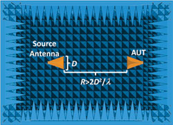
Figure 1 Measurement configuration for the gain-transfer method inside an anechoic chamber.
The receive antenna is placed in the far field of the source antenna where R denotes the respective separation distance, λ denotes the maximum dimension of the antenna and ldenotes the operating wavelength as illustrated in Figure 1. The gain-transfer method is then calibrated by measuring the received power with the gain standard. After replacing the gain standard, the AUT is rotated in the principal plane and the received power is converted to an antenna gain estimate at each angle. Note the source antenna transmits constant power across all measurements.3
NUMERICAL METHODS
Modern full-wave and asymptotic CEM methods, available in commercial software packages such as FEKO, offer several options for either computing or approximating the relationships between electromagnetic fields and currents. Full-wave CEM methods accurately solve Maxwell’s equations without approximations, while asymptotic CEM methods achieve a solution with limited resources by operating with underlying assumptions.Vigilance is then required from the user to model the problem well within those approximations. Fortunately, an increase in electrical size further validates the assumptions underlying asymptotic CEM methods and improves the accuracy of the final results. In response, software companies offer asymptotic methods such as physical optics (PO) and the full-wave finite element method (FEM) hybridized with method of moments (MoM) to assist with solving large and complex problems.
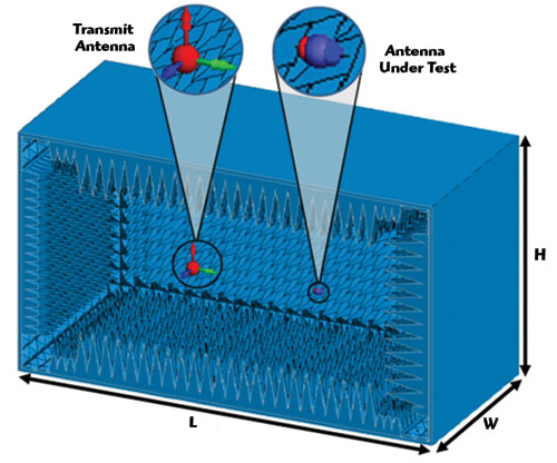
Figure 2 Simulation configuration along with the dimensions for an anechoic chamber model.
In addition, several features can facilitate efficient modeling practices. For example, thin wire approximation, an inherent MoM feature, solves wire structures with minimal resources by discretizing thin cylindrical shapes into linear segments rather than a surface mesh. Domain decomposition minimizes computational resources by solving the far field pattern of an arbitrary source antenna in an isolated environment, which becomes an imported source for subsequent simulations. Modelling an ideal receive antenna involves a similar process. Two hybridized CEM methods, namely MoM/FEM4 and MoM/PO,5-7 as well as efficient modeling practices facilitate the characterization of anechoic chambers and antenna measurement techniques.
CHAMBER MODEL
A custom anechoic chamber with a rectangular down-range cross-section (i.e. W × H) was modeled to fit within a physically limited volume. The chamber dimensions are 17' H × 24' W × 32.5' L as shown in Figure 2, where blue represents absorbing material. The center of the quiet zone is 10' from the receiving wall and measures 6' H × 6' W × 6' L. The source antenna is modeled 20' from the receiving wall as shown left of center in Figure 2.
A central patch of two side walls, receiving wall, floor and ceiling were modeled with large pyramidal absorber surrounded by small pyramidal absorber as illustrated in Figure 1. The absorbing material was modeled with typical values for both the dielectric constant and loss tangent.1
CHAMBER CHARACTERIZATION
Disturbances inside the quiet zone of an anechoic chamber were characterized with full-wave and asymptotic CEM methods. The characterization employed a custom low-gain source antenna designed to increase reflections off the surrounding walls and therefore represent a worst-case scenario. Electric fields in the quiet zone were computed in the explicit presence and then absence of the anechoic chamber. The ratio of these two results produced a systematic error term that identified quiet zone disturbances imposed by the anechoic chamber.
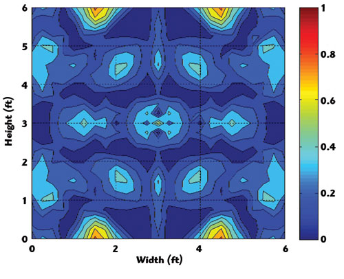
Figure 3 Quiet zone error imposed by the anechoic chamber when operating at 500 MHz.
A rigorous characterization was initially performed on the chamber with MoM/FEM. Negligible disturbances (i.e. less than 1 dB), illustrated in Figure 3, were imposed by the low-gain source antenna when operating at 500 MHz, which validated both the chamber performance and the respective characterization process. A characterization was then performed on the chamber with MoM/PO when operating at 500 MHz. The difference between the full-wave and asymptotic CEM methods is illustrated in Figure 4.1
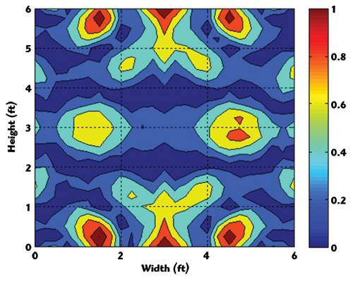
Figure 4 Quiet zone error imposed by MoM/PO when operating at 500 MHz.
The approximations associated with the asymptotic method imposed negligible error (i.e. less than 1 dB), which validated MoM/PO as an effective characterization tool for anechoic chambers. Additionally, the underlying assumptions become more valid as the operating frequency increases. The approximations therefore become more accurate and the error term is further reduced. As a result, engineers can confidently replace rigorous full-wave methods with asymptotic methods and increase the frequency within the confines of the available resources.
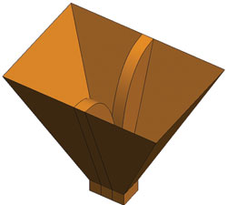
Figure 5 Dual-ridge horn model represented both the source antenna and calibration gain standard.
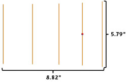
Figure 6 Yagi-Uda model used for co-polarization antenna measurments.
MEASUREMENT EMULATION
Asymptotic CEM methods have provided an opportunity to emulate antenna measurement techniques in the explicit presence of the anechoic chamber. Specifically, the gain-transfer method was validated for both co-polarization (Co-Pol) and cross-polarization (X-Pol) antenna gain measurements using a Yagi-Uda antenna and a shunt-fed slanted V-dipole antenna, respectively.
Figure 7 H-plane gain for a Yagi-Uda antenna, across all angles (a) and at broadside (b).
A dual-ridge pyramidal horn, illustrated in Figure 5, represented both the arbitrary source antenna as well as the calibration gain standard with well-known characteristics (i.e. 6.618 dB broadside gain). The source antenna radiated 10 mW of power at an operating frequency of 1000 MHz across all simulations.
Recent advances in computational resources have helped modern workstations emerge as a cost effective simulation tool. The following simulations were performed on a workstation with 256 GB of shared memory and 2 Intel Xeon E5-2650 CPUs with 8 cores per physical CPU operating at 2 GHz. The simulation at each angle with the explicit presence of the anechoic chamber was solved on all 16 available cores, which required 45 minutes of computational time and 220 GB of memory.
CO-POLARIZATION
The emulated gain-transfer method was initially validated with a Yagi-Uda antenna as illustrated in Figure 6. The vertically polarized antenna facilitated a single plane of electric symmetry to minimize computational resources. These simulations considered angles that spanned from -180° to 180° in 3° increments.
First, the H-plane gain of the AUT was computed with a standard MoM simulation. Next, the gain-transfer method was emulated with a 300 foot (i.e. electrically large) separation distance to compute the co-polarization (Co-Pol) antenna gain. The gain-transfer method was then emulated with a 10 foot separation distance. Finally, the gain-transfer method was emulated with the explicit presence of the anechoic chamber, while maintaining a 10 foot separation distance. The results are illustrated in Figure 7 where GTM refers to the gain-transfer method.
An electrically large distance between the source antenna and the AUT provided an excellent uniform plane wave approximation. Therefore, near perfect agreement between the standard MoM solution and ‘GTM-300’ was achieved, which validated the gain-transfer method as an antenna measurement technique. Although the AUT was still within the typically recognized far field region, emulating the gain-transfer method with a 10 foot separation distance imposed minimal yet distinct degradations in the uniform plane wave approximation and ultimately the antenna gain estimates.
The difference between ‘GTM-300’and ‘GTM-10’ quantifies the error imposed by smaller separation distances. Finally, a quantifiable error term was introduced into the final antenna gain estimate when the gain-transfer method was emulated in the explicit presence of the anechoic chamber.
CROSS-POLARIZATION
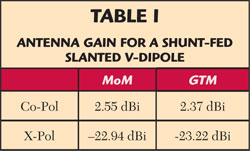
Estimating the cross-polarization (X-Pol) antenna gain in the explicit presence of the anechoic chamber provided the insight necessary to identify an additional systematic error term. A shunt-fed slanted V-dipole, illustrated in Figure 8, was arranged into vertical and horizontal orientations when estimating the co-polarization and cross-polarization antenna gains, respectively. In contrast, the source and calibration antennas maintained a vertical orientation throughout the emulated measurement process. The estimated antenna gains were then compared with free-space MoM simulations as listed in Table 1.
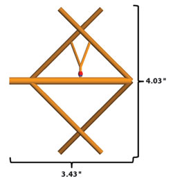
Figure 8 Shunt-fed slanted V-dipole model used for cross-polarization antenna measurements.
The shunt-fed slanted V-dipole, with smaller dimensions, experienced a more uniform illumination than the Yagi-Uda antenna. A smaller systematic error was therefore introduced by the limited separation distance. As a result, remarkable accuracy was achieved at the relatively low levels associated with cross-polarization measurements, which further validated the gain-transfer method.
CONCLUSION
Both full-wave and asymptotic methods were utilized to support several engineering communities. The results have shown that engineers can characterize the quiet zone behavior of anechoic chambers, which provides critical insight during the design process. Antenna engineers can determine the effect of quiet zone disturbances during an antenna characterization process. Measurement engineers can validate antenna measurement techniques and predict the respective performance when operating under non-ideal conditions. Managers can more accurately predict the performance levels and costs associated with purchasing or refurbishing measurement equipment. In conclusion, excellent agreement across various simulations allows several engineering roles to make more informed decisions based on quantifiable error terms.
References
- D. Campbell, G. Gampala, C.J. Reddy, M. Winebrand and J. Aubin, “Modeling and Analysis of Anechoic Chamber Using CEM Tools,” Applied Computational Electromagnetics Society (ACES) Journal, Vol. 28, No. 9, September 2013, pp. 755-762.
- D. Campbell, G. Gampala, C.J. Reddy and J. Aubin, “Simulating Antenna Measurements in an Anechoic Chamber,” 35th Annual Meeting & Symposium of the Antenna Measurements Techniques Association, October 2013, pp. 265-268.
- C. Balanis, “Antenna Theory: Analysis and Design,” 3rd ed., John Wiley & Sons Inc., Hoboken, NJ, 2005.
- M. Bingle, J. Tonder and U. Jakobus, “Acceleration of the Hybrid FEM/MoM Technology in FEKO With the Multilevel Fast Multipole Method,” 10th International Workshop on Finite Elements for Microwave Engineering, October 2010.
- U. Jakobus and F.M. Landstorfer, “Improved PO-MM Hybrid Formulation for Scattering From Three-Dimensional Perfectly Conducting Bodies of Arbitrary Shape,” IEEE Transactions on Antennas and Propagation, Vol. 43, No. 2, February 1995, pp. 162-169.
- I.P. Theron, D.B. Davidson and U. Jakobus, “Hybridization of the Method of Moments With a UTD Treatment of a Conducting Cylinder,” Proceedings of the 8th Biennial IEEE Conference on Electromagnetics Field Computation, June 1998, p. 107.
- U. Jakobus, “Overview of Hybrid Methods in FEKO: Theory and Applications,” 2010 International Conference on Electromagnetics in Advanced Applications (ICEAA), September 2010, pp. 434-437.