
One of the most important aspects in choosing an electronic measurement instrument is dynamic range; however, it is generally not enough to simply compare parameters stated in data sheets. The following discussion explains the relationships among parameters to help understand and evaluate spectrum analyzer dynamic range specifications.
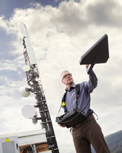
Figure 1 Identifying weak interfering signals in the presence of high signal levels from nearby transmitters.
When monitoring mobile phone interference in urban areas (see Figure 1), test engineers are frequently faced with the problem that the interference signals are weak, often below the noise floor of the measuring instrument, such as a spectrum analyzer. In such situations, greater sensitivity is typically achieved by reducing the input attenuation, resolution bandwidth (RBW) and reference levels and by using a preamplifier. In this way, the noise floor of the instrument is lowered to a level where the interference signals are visible. The disadvantage of this approach is that the instrument’s immunity to stronger signals in the vicinity is reduced. Strong signals may drive devices in the signal chain to operate in nonlinear regions, generating unwanted artifacts such as harmonics, intermodulation products and interference. Artifacts such as second harmonics, which occur at twice the frequency of the input signals, will appear in the spectral display the same as actual signals in the vicinity, and they can be mistaken for interfering transmitters in the radio network (see Figure 2).
DYNAMIC RANGE
High dynamic range enables a high performance test instrument such as a spectrum analyzer to suppress such pseudo signals or keep them as small as possible. Dynamic range is the span where the minimum to maximum strength signals can be detected and measured before unwanted artifacts appear above the noise floor. As a rule, the greater this span or the smaller the amplitude of the artifacts, the higher the dynamic range and the more unlikely the artifacts will be mistaken for real signals. A system design goal is to maximize the intermodulation free dynamic range (IMFDR), where all undesirable intermodulation is below the noise floor. The IMFDR of a measuring instrument is defined as the dynamic range just before the second- or third-order intermodulation products emerge from the noise.
The term high dynamic range (HDR) used for spectrum analyzers and radio receivers refers to the ability of the instrument to reliably record small signal levels, such as those from a mobile phone, in the presence of much larger signals. To use an acoustic analogy, this is like a high quality microphone’s ability to pick up the fine tones of a flute without significant loss when the flute is played adjacent to an operating jackhammer. This requires a balance between high sensitivity for small level signals and simultaneous immunity to saturation from large signals.
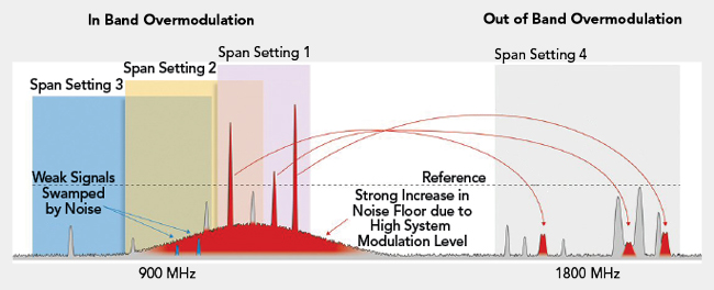
Figure 2 Receiver nonlinearity may create spurs that appear as real signals, in this case harmonics around 1,800 MHz.
While HDR is important for error-free measurements, spectrum analyzer dynamic range is not a rigid criterion. It can change according to the level of the required signal or signals and the measurement settings of the instrument. For this reason, one must consider at least two types of unwanted artifacts from nonlinearity: harmonics and intermodulation.