
Harmonics - Second-order harmonics, for example, occur at twice the frequency of the input signal. Higher-order (i.e., nth-order) harmonics occur at n times the frequency of the input. In contrast with intermodulation, they occur when only a single signal is present, particularly when RF components in the instrument, such as amplifiers and mixers, are driven beyond their linear ranges with increasing power level.
Intermodulation - Intermodulation also occurs when RF components are operated in their nonlinear regions. Unlike harmonics, they are not simple multiples of the individual frequencies, rather the “mixing” of the input frequencies. At least two signals, or tones, are required, which mix together to produce new frequencies. For example, the second-order intermodulation frequencies of the frequencies f1 and f2 are f1 + f2 and f2 – f1 and the third-order intermodulation frequencies are 2f1 + f2, 2f2 + f1, 2f1 – f2 and 2f2 – f1.
SIGNAL LEVELS
If the level of the input signal changes, the level of the second-order artifacts in dB changes by 2x the magnitude of the input change; the level of the third-order artifacts changes by 3x the magnitude of the input change. If the input signal level changes by 10 dB, for example, the levels of the second-order harmonics and intermodulation products increase by 20 dB, and the third-order artifacts increase by 30 dB.
Considering the dynamic range of an instrument, the input attenuation plays a prominent role determining the so-called intercept points, defined as follows:
- IP2/SOI: the second-order intercept point, based on the intermodulation products.
- IP3/TOI: The third-order intercept point, based on the intermodulation products.
- SHI: The second-order intercept point, based on harmonics.
- THI: The third-order intercept point, based on harmonics.
The values for IP2/SOI, SHI, IP3/TOI and THI automatically change with the input attenuation of the instrument. To accurately and meaningfully compare the data sheet values of various instruments, the specified dynamic range or the corresponding parameters for immunity and sensitivity should be based on the same system settings. Typically, the intercept points are specified with an input attenuation of 0 dB. In all other cases, the values for IP2/SOI, SHI, IP3/TOI and THI must be reduced by the attenuation for the values to be compared.
INTERCEPT POINTS
The output power at the input signal frequency and its harmonics are linearly related to the input power until the components in the signal chain near saturation. If the linear relationships are extrapolated as the input power increases, the output signal level will intersect the level of the unwanted artifacts. For third-order intermodulation, the level difference and the dynamic range between the third-order products and the target signal is 0 dB. This intersection of the target signal and the third-order intermodulation signal is called the TOI or IP3 value, i.e., the intercept point of the third-order intermodulation products or the third-order intercept point. This value indicates the theoretical level where the signals are equal.
The other intercept points are defined similarly, i.e., IP2/SOI, SHI and THI. SHI is an informative indicator of an instrument’s dynamic range when making a high sensitivity measurement of weak signals in the presence of a single strong signal that generates harmonics in the instrument. When the instrument is saturated by a single signal, only the harmonics of the signal are produced. Where the intermodulation is caused by the presence of two or more input signals of comparable amplitudes, the THI is more relevant.
The intercept points depend on the selected system settings, whether second- or third-order harmonics or intermodulation. Again, when comparing instrument performance, the settings should be the same. It is customary to specify intercept points based on the highest system sensitivity, i.e., at the lowest settings for the input attenuation and reference level. Most companies specify the IP2 and IP3 as typical values.
DANL
Intercept points are one of two quantities important to determining an instrument’s IMFDR. The other is the displayed average noise level (DANL). The intrinsic noise of an instrument determines the lower limit of measurement, i.e., the sensitivity of the measuring system. The lower the noise floor, the greater the dynamic range. DANL depends on the RBW setting, the system sensitivity or noise figure (NF) and thermal noise. For spectrum analyzers and receivers, -174 dBm, the level of thermal noise, is the physical lower limit of noise power at 300 K, although it can be reduced by cooling the hardware.
When evaluating dynamic range, the DANL or NF should be determined using the same instrument settings used for IP2 and IP3. Any preamplifier connected to the instrument must be inactivated. Although better NFs can be achieved using a preamplifier, the IP2 and IP3 will be degraded. The DANL is generally specified in data sheets as a guaranteed value.
ITU RECOMMENDATIONS
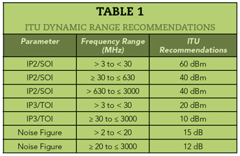
The International Telecommunication Union (ITU) has issued a guideline to better assess dynamic range. The recommendations in the ITU Handbook of Spectrum Monitoring do not refer specifically to spectrum analyzers, rather more generally to monitoring receivers and radio direction finders. In addition to establishing methods to determine dynamic range parameters such as IP3 and NF, the ITU specifies absolute values for different frequency ranges.
As well as the ITU’s numerical recommendations, presented as values in a table (see Table 1), a graphical representation of the parameters can show dynamic range in a way that makes the relationships easier to understand and enable quick and easy performance comparisons. Figure 3 shows a triangle constructed from the values of DANL, IP2 and IP3, where the area of the triangle represents the dynamic range. Increasing the area of the triangle corresponds to greater dynamic range. The values shown in the figure correspond to the ITU recommendations for the frequency range from 20 MHz to 3 GHz: a NF of 12 dB, an IP2 of 40 dBm and an IP3 of 10 dBm.
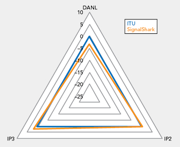
Figure 3 Graphical performance metric plotting DANL, IP2 and IP3, comparing the ITU recommendation for an ideal receiver with the performance of the SignalShark spectrum analyzer. (Source: Narda STS).
The triangle diagram can be used to compare spectrum analyzer dynamic range performance relative to the ITU recommendations. Figure 3 illustrates this by including the performance of the SignalShark spectrum analyzer from Narda Safety Test Solutions. The NF of this device in the corresponding frequency range is 15 dB, 3 dB higher than the ITU recommendation, which is reflected by the smaller DANL value of the triangle. The IP2 above 20 MHz matches the ITU recommendation and the IP3 is better than the ITU recommendation by 2 dB. Overall, the triangle for the SignalShark almost matches the ITU recommendations above 20 MHz, graphically representing the low noise and linear performance of the spectrum analyzer.
The performance of a spectrum analyzer, monitoring receiver or radio direction finder reflects no single component in the signal processing path, rather the combination of all the components in the signal chain, including the analog-to-digital converter and the signal processing architecture of the RF front-end. To improve dynamic range, receivers often include preselectors or filter banks to suppress frequency ranges that may overload the front-end and degrade performance. Using low noise preamplifiers and minimizing the noise of the first mixer stage help set a low intrinsic noise floor of the receiver.
SUMMARY
The dynamic range of an instrument such as a spectrum analyzer is not a fixed quantity easily compared by reviewing the data sheets of commercial instruments. Dynamic range depends on interrelated factors reflecting the input signal level and the instrument’s settings. Comparing instruments requires understanding of all the parameters determining the dynamic range and how they depend on the instrument’s settings. The ITU guidelines and triangle diagram are helpful for assessing instrument performance and comparing products from different manufacturers.