
Down-Conversion
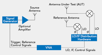
Figure 3 OTA measurement setup.
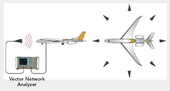
Figure 4 Large vehicle shielding and propagation testing.
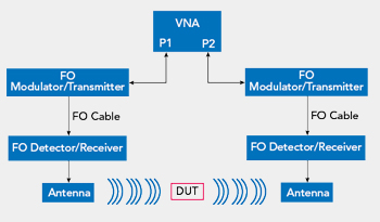
Figure 5 Test setup using fiber-optic detectors and receivers.
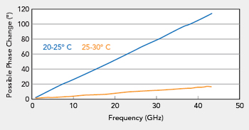
Figure 6 Phase change of a 4 m cable vs. frequency and temperature.
Another strategy to reduce cable insertion loss is down-converting the mmWave signal to a lower frequency before transmitting it through the long interface cables (see Figure 3). In this setup, a signal generator is placed physically close to the transmit antenna, to minimize cable length and insertion loss. The AUT and a reference antenna, if needed, receive the test signal, which is down-converted with mixers, along with the local oscillator (LO) and IF distribution hardware. The lower frequency IF signal has less insertion loss from the cable run to the VNA. For long distances, this will significantly reduce the insertion loss: the same cable with 4 dB/m loss at 40 GHz may only have 1 dB/m loss at 4 GHz.
While this approach reduces the loss of the received signal from the VNA, the cable carrying the LO signal to drive the mixer will still have high insertion loss, because the LO frequency is close to the original microwave test frequency. Subharmonic mixing can be used to lower the LO frequency but this will often reduce the dynamic range of the measurement. Also, the down-conversion approach complicates the hardware setup, as the IF and LO signals must be distributed, and the LO must be amplified to compensate for cable loss, which introduces noise and distortion to the measurement. Another drawback is the complex calibration required to compensate for the effects introduced by down-converting the mmWave test signal to IF. This complexity limits the available calibration and de-embedding techniques and the flexibility of the measurement.
Fiber-Optic Links
For applications where the distances are 100 m or greater - characterizing the shielding and propagation performance of large vehicles, like ships and aircraft (see Figure 4) - using coax cables at microwave and mmWave frequencies is often not practical. One solution for this application is using fiber-optic (FO) cables to connect the VNA with the test antennas in the setup (see Figure 5). At microwave frequencies, FO cables have very low insertion loss, on the order of 0.1 dB/30 m at 850 nm. This low loss enables them to be used over long lengths without significantly affecting the measurement signals. A FO transmitter and receiver are used to convert the RF signal to optical in the transmit path and back to RF in the receive path. As with the down-conversion setup, the FO solution relies on active components in the signal path between the DUT and the VNA, which adds complexity and cost. Because electrical-optical (EO) modulation is lossy, the EO to optical-electrical (OE) conversion has poor noise figure, which reduces any dynamic range advantage gained from the lower insertion loss. Also, because the distances are typically very long, the setup can be difficult.
Another issue with VNA measurements over distance is the phase stability of the cable connecting the VNA port and the DUT. Changes in position or ambient temperature can cause small deviations in the electrical length of the cable, enough to produce several degrees of phase shift at microwave frequencies. Limiting movement or temperature change to minimize the phase drift is difficult, especially for long distances outdoors. Figure 6 shows an example of the phase change using a quality, 4 m long cable over two 5°C temperature ranges. Even with these relatively moderate temperature ranges, the phase change is significant. For outdoor applications, where cable lengths are typically longer and the temperature swings larger, the phase change will be even greater.
Restating, the main issue with measuring over long distance is getting the VNA test signal to and from the DUT without significant loss or distortion, which will reduce the accuracy and stability of the measurement.
MODULAR VNA
A novel solution to this is the concept of a modular VNA. Instead of having a single instrument where the ports are co-located in a single chassis, a modular VNA has independent, portable modules placed close to the DUT to minimize the cable lengths to the ports (see Figure 7).
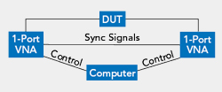
Figure 7 Modular VNA setup.
With microwave source and measurement capability in the portable modules, the issue of insertion loss and distortion caused by long coaxial or fiber interconnects is eliminated, improving the stability and accuracy of the measurements. Eliminating active components in the measurement path, such as the EO-OE conversion, improves the noise performance and simplifies calibrating the long distance measurement. The portable ports enable the calibration planes to be essentially at the DUT ports, without intervening hardware and flexible VNA calibration and de-embedding techniques can be used, yielding more accurate measurements.
To illustrate the straightforward calibration, consider an OTA setup using horn antennas and calibrating with the line-reflect-match (LRM) technique (see Figure 8). For LRM calibration, the line standard is just the OTA path between the two antennas, and a simple flat sheet of metal will create the reflect and match standards. For the reflect standard, the sheet is placed to completely block the antenna, which reflects the signal power back to the antenna and the VNA. The algorithm does not require precise knowledge of the reflect standard, so the positioning accuracy of the sheet is not as demanding as might be expected. The match standard is formed with the sheet at a 45 degree angle from the boresight of the antenna, so the sheet reflects almost all the signal from the antenna and appears like a perfect match.
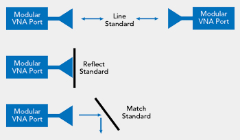
Figure 8 Calibrating a modular VNA with LRM standards.
While portable, independent VNA ports eliminate the interconnect issues, they do require precise synchronization between the ports to ensure accurate S-parameter measurements (i.e., with magnitude and phase components). Phase synchronization between ports in a VNA where the source/LO synthesizers are separated over long distances is complex. The synchronization must account for source and receiver clocking and triggering in a way that keeps the relative phase stable within a few degrees at the measurement frequencies. This can be difficult to accomplish in a single chassis instrument; to achieve this precision over distances greater than 100 m requires a new design paradigm.
One example of such a modular VNA architecture is Anritsu’s ShockLine™MS46131A VNA with the PhaseLync™synchronization option. The MS46131A is a 1-port VNA with an independent source and receiver, frequency coverage to 43.5 GHz and small size to facilitate connecting to antennas and other DUTs. With optional circuitry and cabling, a pair of the PhaseLync VNAs can be synchronized to act as the ports in a distributed 2-port VNA and support measurement setups where the ports are separated by more than 100 m (see Figure 9). The PhaseLync system includes phase compensation to improve measurement stability with mechanical and thermal changes from the environment.
SUMMARY
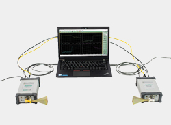
Figure 9 Distributed 2-port VNA using individual 1-port VNAs.
For VNA applications like far-field antenna and large vehicle shielding and propagation measurements, several methods can address the insertion loss and other negative aspects of long interconnect cables. A modular VNA architecture presents a new alternative for S-parameter measurements by eliminating long cable runs and simplifying the test setup. Bringing the VNA ports to the DUT, the modular architecture enables flexible calibration and de-embedding techniques, which improve measurement stability and accuracy.