
A key aspect of microwave vector network analyzer (VNA) testing is minimizing the measurement effect of the interface to a device under test (DUT). Using high stability, low insertion loss test port cables and applying techniques like reference plane extension and fixture de-embedding, VNA users have been very successful for years in minimizing the effect of the path from the VNA port to the DUT for typical microwave and mmWave S-parameter measurements. These techniques are less successful with longer distances or larger DUTs and at high frequencies, as cable insertion loss and instability grow significantly, making it more difficult to compensate for the path using typical bench VNA techniques.
HANDLING LONG DISTANCES
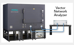
Figure 1 Antenna chamber with external VNA.
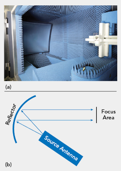
Figure 2 OTA test chamber using a reflector (a), with the corresponding ray diagram (b).
Long cable runs between the VNA port and the DUT occur in applications like over-the-air (OTA) testing in indoor chambers and outdoor ranges, as well as measuring the RF/microwave characteristics of large vehicles, like ships and aircraft. A key issue in these applications is the insertion loss of the cable at microwave frequencies reducing the dynamic range of the VNA measurements.
Take, for example, a 5G antenna operating in one of the mmWave bands (i.e., FR2), measured in a typical test chamber (see Figure 1). At 40 GHz, expensive, quality coax cabling has approximately 4 dB/m insertion loss. For a moderately sized antenna test chamber, 2.2 x 1.98 x 1.2 m, several meters of cable are needed to connect the external VNA to both the antenna under test (AUT) and the feed antenna inside the chamber. Assuming a moderate distance of 5 m between each VNA port and the antennas inside the chamber, the cables will add about 40 dB of loss to a transmission measurement, significantly reducing the effective dynamic range of the measurement.
Far-Field Measurements
Many OTA antenna measurements done at far-field distances - where the outgoing wave front from the antenna is essentially planar - significantly increase the size of the chamber and the cable length between the VNA and AUT. Antenna measurements are made in the far-field to simulate the transmission conditions at the normal operating distance from the antenna. The Fraunhofer equation is used to calculate where the far-field region begins for a given antenna:

where D is the largest dimension of the antenna and λ is the wavelength. For a 40 GHz antenna with an approximate diameter of 6 cm, the far-field distance starts at 1 m. Considering an antenna with d = 15 cm, which is about the length of a smartphone, the far-field distance is approximately 6 m at 40 GHz. As the antenna size increases, far-field measurements will require chamber sizes to grow rapidly, increasing the effects of cable insertion loss on OTA testing.
One way to attain the far-field distance while minimizing the size of the chamber is placing a reflector in the chamber, which increases the effective transmission distance within a given volume (see Figure 2). Compact antenna test ranges (CATR) use a reflector to minimize the chamber’s dimensions for a given test distance, which reduces cable lengths and insertion loss. While using the reflector does reduce the size of CATRs, it limits the size of the DUT the chamber can test. The region where a reflector can maintain the plane wave, or focus area, bounds the size of the DUT that can be tested (see Figure 2b). As the size of the DUT increases, the reflector must grow significantly to widen the focus area, diminishing any volume reduction gained by using reflectors.