
Technical Feature
Two-tone vs. Single-tone Measurement of Second-order Nonlinearity
Darioush Agahi, William Domino and Nooshin Vakilian
Conexant Systems Inc.
Newport Beach, CA
This article describes how to correctly find the second-order intercept point (IP2) from one- and two-tone tests, and presents measurement results in support of the theory.
Relation Between Two-tone and One-tone Tests For Second-order Nonlinearity
Second-order nonlinearity is a phenomenon that is important in direct conversion receivers (DCR). Test results for this kind of nonlinearity are shown, which can be used to predict the direct current (DC) offset, both with single-tone or two-tone signals. A two-tone condition is shown pictorially in Figure 1 .
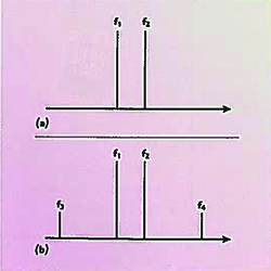
Fig. 1 Two-tone condition; (a) input and (b) output.
The relationships between f1 , f2 and f3 , f4 are
f3 = f2 - f1
and
f4 = f2 + f1
This shows that the unwanted output frequency components are mathematically related to the input tones. To have better insight into the relationship between undesired components and the input terms, a more rigorous derivation is needed. Here is an attempt in showing the derivation with some simplifications.
Using a Taylor series expansion, the output voltage Vo of the gain stage as a function of input voltage vi can be modeled as
Vo (t) = k1 vi (t) + k2 vi 2 (t) + k3 vi 3 (t) + k4 vi 4 (t) +k5 vi 5 (t) + … (1)
For a two-tone input
Vi (t) = A cos( w1 t) + B cos( w2 t) (2)
Inserting Equation 2 into Equation 1 and using well-known trigonometric equalities
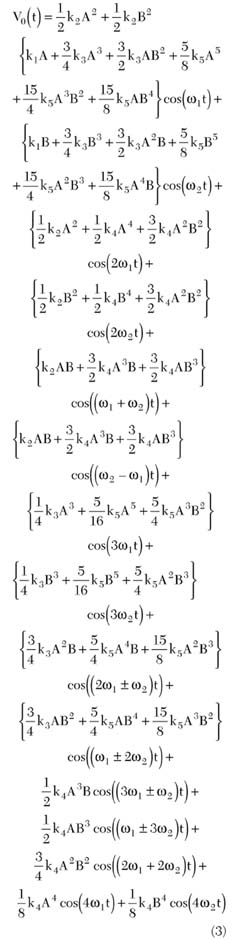
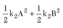
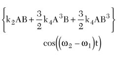
In this study the sum term is ignored since the baseband filters of the device will reject it. However, the difference term is retained, since it can be used to evaluate the DC offset of the receiver. Note that in practice the input tones are chosen such that the difference can produce a tone near DC, that is, inside the receiver's baseband bandwidth. From Equation 3, the pure DC terms are
and the difference term is
Under a single tone condition, B is set to zero and the DC created is
For a two-tone test and only second-order nonlinearity, the higher order terms are ignored and the coefficient of the output is then k2 AB. This coefficient is the peak amplitude voltage of the difference frequency output. When calculating the second-order intermodulation product (IM2) it is the measured power that is required, so the RMS output voltage
is needed.
The ratio of the output of the one-tone test to the output of the two-tone test is then given by
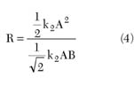
The numerator is the DC output voltage from the one-tone test, and the denominator is the ACRMS voltage from the two-tone test. Remember that in the one-tone test, the input amplitude is A, while in the two-tone test the amplitudes are A and B. Assuming equal tones for the two-tone test (B = A), then
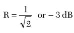
This simply says that the root mean square (RMS) alternate current (AC) signal created from a two-tone test is 3 dB higher than the DC offset created from a single-tone test, when the single-tone test uses the same amplitude as one of the two-tones. In other words, DC voltage (one-tone) = AC RMS voltage (two-tones) - 3 dB.
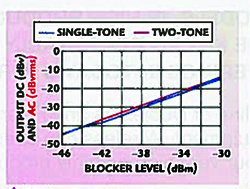
Fig. 2 DC and AC (rms) outputs vs. blocker input level.
This is verified by measurement in the graph shown in Figure 2 , where the receiver under test exhibits a significant amount of second-order nonlinearity. In this test, the single-tone was at 3 MHz offset, while the two-tones were at 3.00 and 3.06 MHz, so a DC IM2 output in dBVDC is being compared to a 60 kHz IM2 output in dBVRMS. The 60 kHz output is expected to be 3 dB higher as derived above. But in the measurement system, there is a low pass response that rolls off by 1.4 dB at 60 kHz. Therefore, the 60 kHz output should be 1.6 dB higher than the DC. This is indeed the case over most of the tested range.
Second-order Intercept (IP2) Calculation From Two-tone and One-tone Measurements
In Figure 3 , the fundamental and second-order output powers vs. input power are plotted for a generic system that has some second-order nonlinearity. The gain is normalized to unity so IIP2 = OIP2. In practice, all quantities are usually referred to the input.
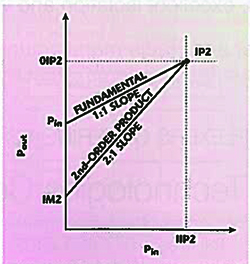
Fig. 3 Fundamental and second-order output powers vs. input power.
By convention, in any two-tone test (including third-order IP3 tests), the power levels plotted refer to one of the input tones and one of the output product tones. Therefore, even though the system has an amount of power applied to it that is 3 dB higher than the power of one-tone alone, only the power of one-tone is plotted, not the sum of both. Likewise, only the IM2 power at the difference frequency f2 - f1 , rather than the sum of powers at both f2 - f1 and f2 + f1 , is plotted.
From the slopes of the curves, we can see that IP2 can be calculated from one set of measurements as
IP2 = 2(Pin ) - IM2
where all quantities are in dBm.
This classical IP2 equation has a resemblance to the much more often used IP3 equation for a two-tone test, which is
2(IP3) = 3(Pin ) - IM3
The next question is how to correctly calculate IP2 when a one-tone test is done and the IM2 product is at DC. The answer must be the same as that found in the two-tone test.
First, the conventions for the one-tone test must be chosen. IP2 is calculated based on the power of the single applied tone (even though this is all the power applied to the system, unlike what is done in the two-tone calculation), and on the DC output power (where the other, higher frequency product, which is at 2f1 , is ignored).
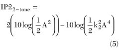
In the two-tone test, as shown previously, inputs of Acos(w1 t) and Acos(w2 t) result in an IM2 product of k2 A2 cos((w2 - w1 )t). The peak voltage of one input is A, while the RMS value is A/√2. Likewise, the peak voltage of the IM2 output is k2 A2 , while its RMS value is k2 A2 /√2. The IP2 calculation from the two-tone test is then IP22-tone = 2(Pin ) - IM2
In the one-tone test, the single input is Acos(w1 t), resulting in a DC IM2 output voltage of k2 A2 /2. The peak input voltage is A, while its RMS value is A/√2. If the classical IP2 calculation is recklessly applied with these quantities, one would obtain
IP21-tone = 2(Pin ) - IM2
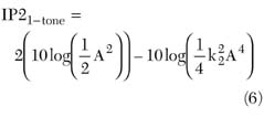
The second term in Equation 6 is 3 dB lower than the second term in Equation 5. This is the same 3 dB difference already identified in the first part of this article. Therefore, the results from a one-tone test are used to calculate IP2 using IP2 = 2(Pin ) - IM2, and 3 dB must first be added to the measurement of the DC IM2 product. Then the result will match that of the two-tone test. Therefore, the correct IP2 equation for a one-tone test, where Pin is the power of the single input tone and IM2 is the power of the DC output, is
IP2 = 2(Pin ) - (IM2DC + 3 dB) (7)
Using the IM2 data presented in the earlier graph, the IP2 is calculated according to IP2 = 2(Pin ) - IM2ACRMS for the two-tone test, and IP2 = 2(Pin ) - (IM2DC + 3 dB) for the one-tone test. The results are plotted in Figure 4 . The calculated IP2 values are found to generally agree.
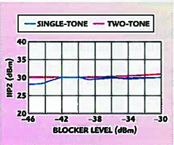
Fig. 4 IP2 values for single-tone and two-tone tests as calculated from IM2 data.
IP2 Requirements for a GSM Direct Conversion Receiver
For a direct conversion receiver, second-order nonlinearity causes any large blocking signal to result in an unwanted DC output. This effect can be characterized using IP2 as the measure of merit. It is desirable that the receiver exhibit maximum IP2.
For consistency, the same equation that is used to calculate IP2 performance from IM2 data must also be used to determine the IP2 requirement from the maximum IM2 that the system can tolerate. The GSM AM suppression specification (from GSM specification 05.05) sets the IP2 requirement for a direct conversion receiver. For the GSM900 band, the single blocker applied is -31 dBm, while the desired signal is at -99 dBm. In order to keep the DC product below -9 dBc, the IIP2 must be
IIP2REQ = 2(Pin ) - (IM2DC + 3 dB)
where the IM2 level is referred to the antenna. The value is calculated as
IIP2REQ = 2(-31 dBm) - ((-99 dBm - 9 dBm) + 3 dB)
IIP2900MHz REQ = +43 dBm at the antenna.
Then, in a receiver with 3 dB of front-end loss due to switches and filters, the IIP2 requirement at the LNA input becomes
IIP2900MHz REQ = +40 dBm
at the LNA input. Likewise, for DCS1800 and PCS1900 receivers with 3 dB front-end loss, the IIP2 requirements at the LNA inputs are calculated to be +42 dBm and +44 dBm, respectively.
Conclusion
Care must be taken when relating the results of two-tone and one-tone tests for IP2. With all tones applied being equal in amplitude, the two-tone test produces an AC RMS voltage that is 3 dB higher than the DC voltage produced by the one-tone test. This must be taken into account consistently when using a one-tone test to determine both IP2 requirements and measured performance of a receiver.
References
1. W.E. Sabin and E.O. Schoenike, Single Sideband Systems and Circuits , Second Edition, McGraw Hill, 1995.
2. B. Razavi, RF Microelectronics , Prentice Hall, 1998.
Darioush Agahi is director of GSM RF Systems Engineering at Conexant Systems Inc. in Newport Beach, CA. Prior to joining Conexant in 1996 he worked for 10 years for Motorola's (GSM) cellular subscriber division. Darioush received his BS degree in electronics in 1981 and his MS degree in medical engineering from George Washington University in 1983. He also received his MSEE degree from the Illinois Institute of Technology in 1993 and his MBA from National University in 1997. Darioush holds twelve US patents. He is a professional engineer (PE) registered in the state of Wisconsin. He may be reached via e-mail at darioush.agahi@conexant.com.
William Domino is a principal engineer for GSM RF Systems Engineering at Conexant Systems Inc. in Newport Beach, CA, where he has been employed since 1992 in the area of digital-radio system architecture development. He received his BSEE degree from the University of Southern California in 1979 and his master's in engineering from California State Polytechnic University in 1985. His interests currently include receiver and transmitter system design for various cellular standards, as well as filter design. In these areas he has one patent issued and 10 patents pending. He may be reached via e-mail at william.domino@conexant.com
Nooshin Vakilian is a systems engineer for GSM RF Systems Engineering at Conexant Systems Inc. in Newport Beach, CA, where she has been employed since 1996 in the area of digital-radio system architecture development. She received her BSEE degree from California State Polytechnic University in 1993 and her master's in engineering from the University of Southern California in 1996. Her interests currently include receiver system design for various cellular standards. She may be reached via e-mail at nooshin.vakilian@conexant.com.