Notch filters may be connected in cascade to improve suppression, having matched impedances of 50 or 75 W at the input and output. Some models integrate several stages in a single package.
Some of the features that may be incorporated in individual products may include anti-aliasing, absorptive input, constant impedance, flat time delay, high rejection/isolation, high linearity, low inter-modulation distortion, high-power rating, high mean time between failures, low insertion loss, high temperature stability and high shock resistance.
Cavity Filters
In cavity filters, Q-factors are high and can be traded against smaller package sizes. Cavity filters are available from 30 MHz to 40 GHz with bandwidth options from less than 0.5 percent to over 66 percent. They offer lower insertion loss, steeper skirt selectivity and narrower bandwidths than discrete component filters. At lower frequencies a helical coil is used to excite the electromagnetic field, while a 1/8 to 1/4 wave capacitively loaded stub is used at higher frequencies. Waveguide designs are used for narrow bandwidths and high-power.
Ceramic Resonator Filters
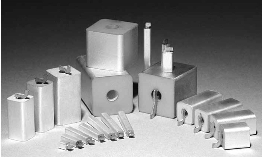
Fig. 4 Coaxial ceramic resonator filters (Courtesy of Skyworks Trans-Tech Inc.).
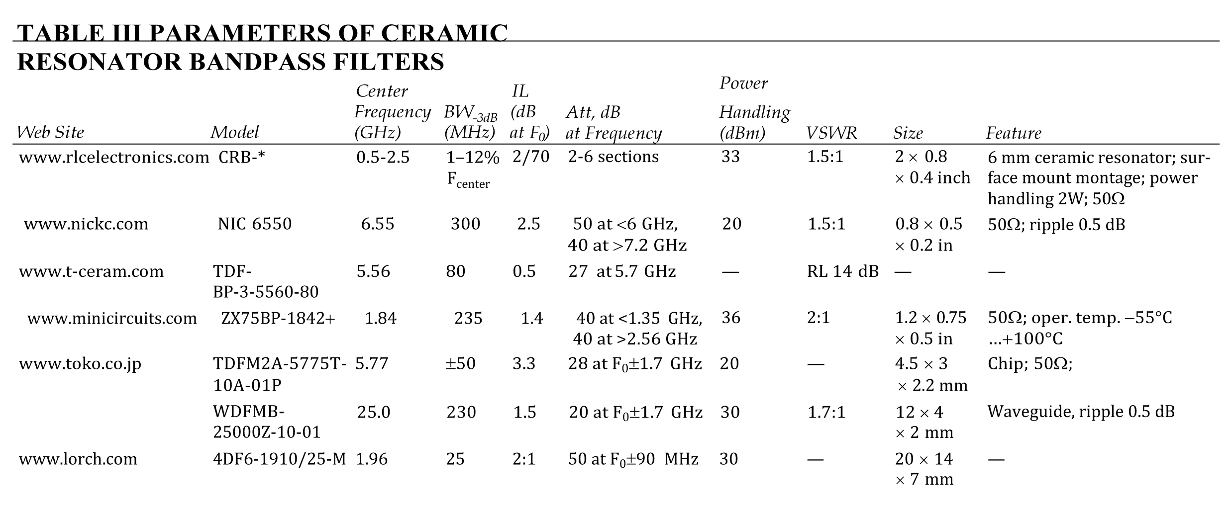
A high-Q dielectric or ceramic resonator is made of a ceramic material with metallized surfaces in the form of a disk, cylinder, or parallelepiped, frequently with an internal hole. Resonators with the internal holes are called coaxial resonators (see Figure 4). Ceramic resonator filters provide cost-effective solutions enabled by their compact low profiles and high Q values. They are typically used at frequencies from 0.4 to 6 GHz, have from 2 to 10 sections and handle RF power up to 10 W. Relative bandwidths are 1 to 10 percent with temperature stabilities of 2 to 11 ppm/°C operating from -40°C to +85°C. Losses are typically low and mechanical durability (resistance to shock and vibration) is high. Table 3 lists some examples.
Microstrip and Stripline Filters
Microstrip consists of a conducting strip separated from a ground plane by a dielectric, or substrate. Stripline is a conductor embedded in dielectric between a pair of ground planes. Suspended substrate stripline consists of a transmission line structure printed on a substrate suspended between two conducting planes (see Figure 5). The conducting planes provide shielding and prevent the excitation of higher order modes.
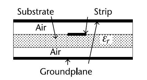
Fig. 5 Cross-section of suspended substrate stripline.
Suspended substrate stripline filters are often used due to their higher Q-factors than printed stripline and microstripline. A suspended substrate filter has a higher unloaded Q, which results in lower passband loss than a conventional stripline filter. In addition, the lack of dielectric surrounding the circuit makes the filter less sensitive to ambient temperature variations. Combining lumped and distributed elements onto one suspended substrate board provides enhanced unloaded Q, lower insertion loss and smaller package sizes, than the use of a single topology.
Tubular Filters
Tubular filters have many advantages over other topologies for bandpass and lowpass filters. Because of their mechanical configuration, they offer very broad stopbands and very high rejection. Using capacitively coupled dielectric spacers, tubular filters are ideal for handling power levels up to 5000 W. Tubular filters are implemented for frequencies from 100 MHz to 20 GHz with bandwidths from 4 to 40 percent and have two to eight sections. They are compact, vibration resistant up to 20 g and operate from -55°C to +85°C.
Waveguide Filters
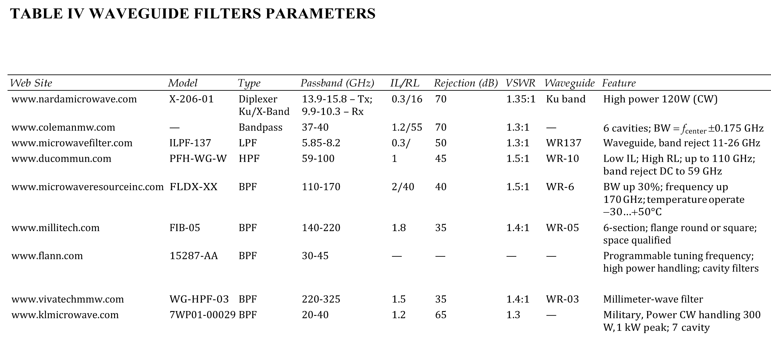
Waveguide filters operate at frequencies from 2.5 to over 300 GHz in the rectangular waveguide TE101 mode. They may have one to 20 sections and passbands from 0.1 to 10 percent. Circular waveguide filters using the TE111 mode can have 2 to 6 sections and relative bandwidths from 0.1 to 1.8 pecent. Compared to coaxial, tubular and microstrip implementations, BPFs and BRFs in waveguide have higher levels of rejection, higher power handling capabilities, the ability to operate in mm and sub-mm wavelength ranges and greater connector choices. They have also been used to realize mechanically tuned filters and diplexers with high transmit and receive channel isolation of not less than 85 dB. In many systems, waveguide filters are more easily integrated with other components in the antenna-feed path. All filter types can be implemented in waveguide. The parameters of some models of waveguide filters are shown in Table 4.