FILTER TOPOLOGIES
The different configurations include:
- Lumped LC (on discrete elements)
- Cavity (combline, interdigital)
- Ceramic (monoblock, resonator)
- Stripline, microstrip, suspended substrate stripline (SSS)
- Coaxial
- Tubular
- Waveguide
- SAW and BAW
- Monolithic crystal
- Thin-film
- YIG (yttrium iron garnet, ferrite)
- MEMS (micro electro-mechanical systems)
Lumped LC filters cover the frequency range from DC to hundreds of MHz with relative bandwidths up to 200 percent. Cavity filters offer high values of Q (to 1000) with a number of sections up to 15. Strip and stripline filters are suitable for surface mount components up to frequencies of about 40 GHz. Tubular filters have increased power handling. Crystal, SAW and BAW filters have rather high Q values. Garnet (YIG) filters enable multi-octave electrical tuning.
Many quantitative characteristics are common among them; for example, increasing the number of filter sections can be used to decrease the relative bandwidth and increase selectivity. However, losses within the passband increase as well as the duration of transients. Size and cost increase as well.
The operating frequency and relative bandwidth of microwave resonators differ depending upon the manufacturing technology (see Figure 2). Thermal properties, environmental factors and the application (transmitter, receiver, GPS/GLONASS, VSB, CDMA, GSM, wireless) depend upon the manufacturing technology as well.
Typical filter performance specifications include:
Insertion Loss (IL) within the bandwidth is proportional to filter Q and inversely proportional to the relative bandwidth at half-power BW-3dB:
IL = 20log10 Q/(Q-1.41/BW-3dB) (6)
Loaded Q (QL) is the ratio of the center frequency to the 3 dB bandwidth of a bandpass filter:
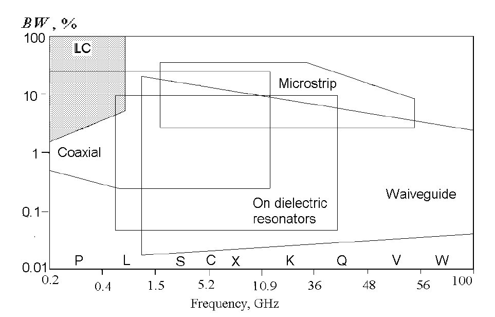
Fig. 2 Operating frequencies and a passbands for various filter technologies
QL = CF/BW-3dB (7)
where CF is the center frequency.
The Frequency Bandwidth of the passband for a given loss is typically defined by the frequencies at the 3 dB points (the loss at band center minus 3 dB); and the stopband, for example, may be defined from the frequency for which the loss is 30 dB greater than the passband peak. The relative bandwidth (percent bandwidth) for BPFs and BRFs is normalized as a percent of the center frequency value. Moreover, values of the minimum and maximum frequencies are specified.
Shape Factor is the ratio of the AFC bandwidth at a given reject level (for example, BW-30dB) and the half power bandwidth (BW-3dB), i.e.
SF = f/fco for LPF; fco/f for HPF; (8)
BW-30dB/BW-3dB for BPF; BW-3dB/ BW-30dB for BRF
Rise Time of the amplitude transient process at the output after an applied impulse is the time that the output signal amplitude changes from 10 to 90 percent of its maximum.
Maximum Input Level (continuous and/or pulse), is specified in accordance with requirements for heat dissipation and/or distortion. For example, in order to decrease geometric size, some manufacturers use ferrite inductive elements, for which loss and magnetic permeability are affected by signal amplitude. Limitations on power handling are inherent in SAW and BAW filters as well.
Return Loss (RL) is the ratio of reflected to incident power or, equivalently, the voltage standing wave ratio (VSWR):
RL = 20 log [(VSWR – 1)/(VSWR + 1] (9)
Ripple is a wave-like variation of the amplitude response within a filter’s passband due to impedance mismatch.
Flatness is the absolute limit of amplitude variation in the passband. It includes ripple due to impedance mismatch as well as the monotonic roll-off at the band edges due to finite Q.
Ringing is a decaying oscillation at the output of a filter due to a transient signal at the input. Overshoot is when a signal or function exceeds its target due to ringing.
Environmental Requirements such as temperature, shock, vibration, moisture and radiation are defined by industry standards. As a rule, components should meet their performance specifications at an input power of no less than 1 W, shock up to 30 g, sinusoidal vibration up to 10 g at frequencies from 5 to 1 kHz, relative moisture of not less than 95 percent, and temperatures between of 40°C and 85°C.
BPF specifications typically include the center frequency, 3 dB bandwidth, lower stopband frequency at an attenuation -30 dB and upper stopband frequency at an attenuation of -30 dB. For higher order filters, ripple is specified both in the passband and in the rejection band. Requirements on input impedance and environmental conditions are included as well.
BRF, or notch filter, specifications typically include the center frequency of the rejection band and attenuation at this frequency, lower and upper frequencies of the stopband for attenuation of -30 dB, and the lower and upper bandpass frequencies. As with the BPF, ripple, impedance and environmental requirements are included as well.
Lumped LC Filters
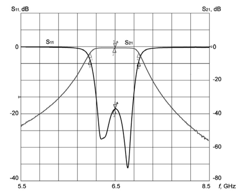
Fig. 3 Typical frequency response of a BPF. (Courtesy of K&L Microwave).
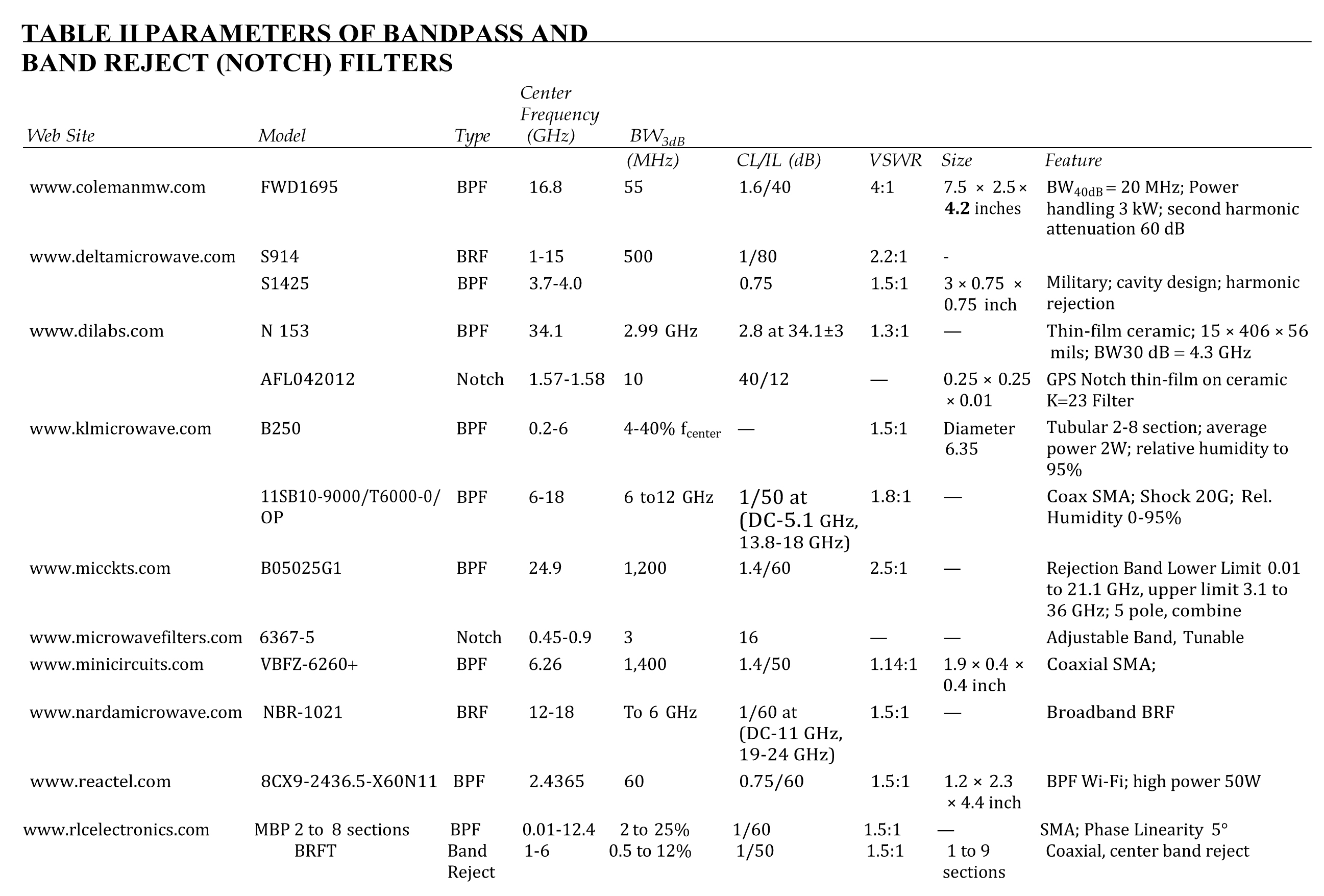
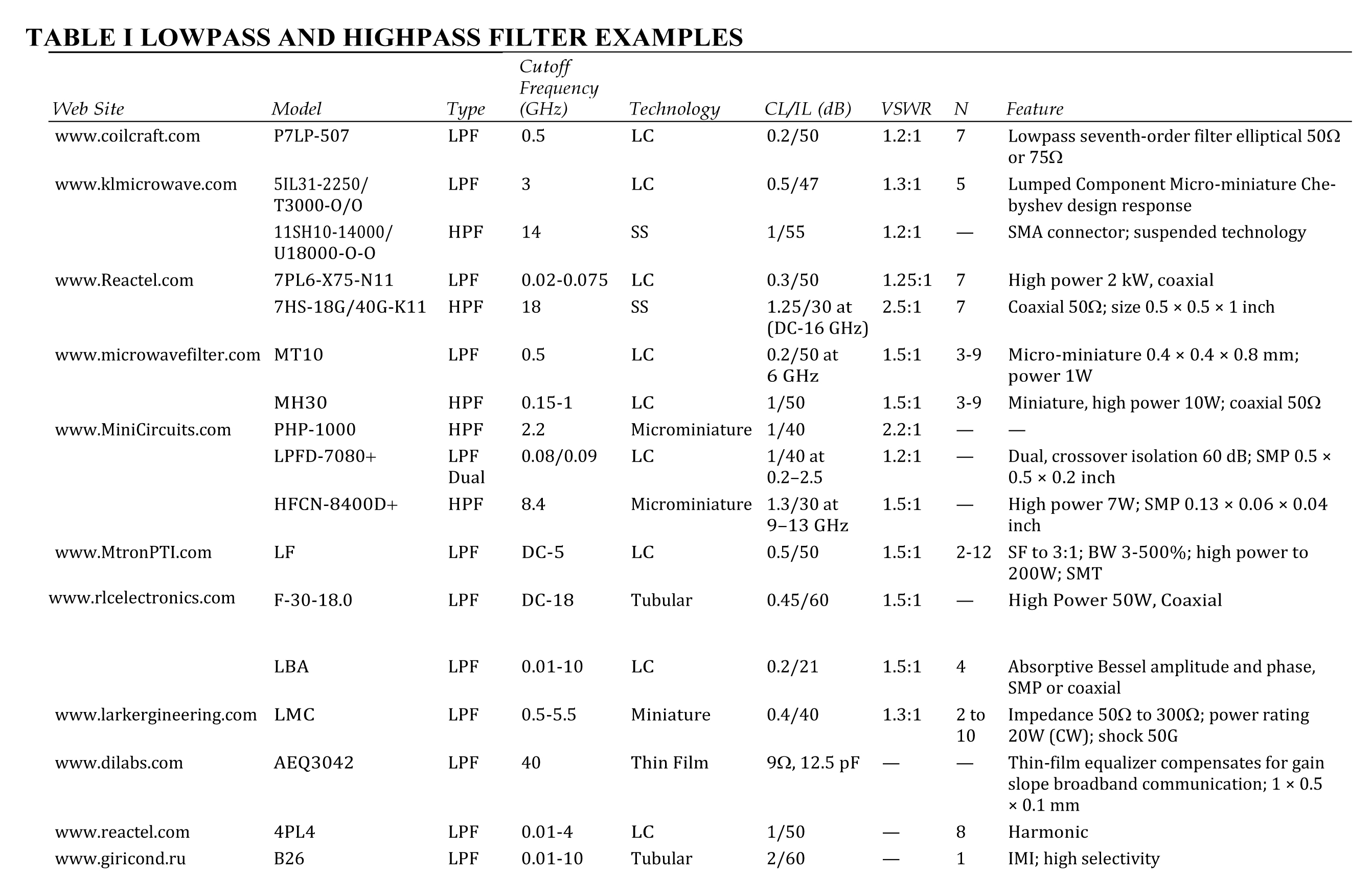
Filters with lumped LC elements using various technologies for frequencies in the RF and microwave ranges are offered by several manufacturers. LPF and HPF examples are listed in Table 1, while several BPF and BRF type filters are presented in Table 2. Figure 3 shows the frequency response of a typical BPF where insertion loss is low and return loss is high within the passband, but rapidly transitions to high insertion loss and low return loss (i.e. rejection) in the regions below and above.
In Table 2, there are several examples of a notch filter. This is a narrowband rejection filter designed to suppress an unwanted concentration of spectral components within a desired band of interest.