
TUTORIAL
MEMS for RF/Microwave Wireless Applications: The Next Wave Part II
Microelectromechanical systems (MEMS) technology is on the verge of revolutionizing RF and microwave applications.1 The requirements of present day and future RF and microwave systems for lower weight, volume, power consumption and cost with increased functionality, frequency of operation and component integration are driving the development of new RF/microwave MEMS components and system architectures. Part I, published previously, presented a brief discussion of RF and microwave system requirements, and then introduced the enabling potential of MEMS to meet these requirements. Part II describes the revolutionary possibilities afforded by MEMS in system integration and novel architectures.
Héctor J. De Los Santos
Coventor Inc.
Irvine, CA
Randy J. Richards
Cary, NC
The interest in MEMS technology for RF and wireless applications stems from the view that, because of its flexibility, it can be exploited to overcome the limitations exhibited by integrated RF devices1 and, in doing so, enables circuits with new levels of performance not achievable otherwise. Thus, the ultimate goal in applying RF MEMS is to propagate the device-level benefits all the way up to the system level to attain unprecedented levels of system performance, as shown in Figure 1. In this section, early examples of circuits exploiting MEMS are presented.
|
|

MEMS Inductor-based Circuits
Inductors are key elements determining the performance of tuned circuits, in particular, impedance matching networks, low noise amplifiers and voltage-controlled oscillators (VCO).2 Improving the gain, power dissipation or phase noise of these circuits has, in turn, led to incorporating MEMS-based on-chip inductors. Perhaps the quintessential example of the improvements brought about by a MEMS inductor is the pioneering demonstration of a tuned CMOS RF amplifier by Chang, Abidi and Gaitan.3 Figure 2 shows a performance comparison obtained from amplifiers, constructed with and without the inductor's substrate removed. Improvements of approximately 12 dB in gain, and a factor of two higher center frequency capability with the MEMS inductor are evident.
|
|

MEMS Varactor-based Circuits
Varactors are essential components wherever circuit tunability is required (for example, in variable matching circuits and VCOs). However, as the move toward more compact form factors persists, and since good semiconductor varactors are incompatible with conventional IC processes, a number of efforts to demonstrate the performance level enabled by MEMS varactors have been undertaken.4,5,6 A recent example is that shown by Dec and Suyama6 who, employing 1.4 pF parallel plate capacitors with a Q of 14 at 2 GHz and fabricated in standard polysilicon surface micromachining technology, demonstrated a 2.4 GHz VCO with a phase noise of 122 dBc/Hz at 1 MHz offset from the carrier and a 3.4 percent frequency tunability range over a 5 V tuning voltage.
MEM Switch-based Circuits
The excellent performance of prototype MEMs switches -- for instance insertion loss and isolation of approximately 0.1 dB and 50 dB, respectively, from DC to 4 GHz7 -- has demonstrated their great potential for replacing lossy and power hungry semiconductor switches in numerous applications, including T/R switches, phaseshifters, switchable filters, cross-bar/multiplexing, tunable antennas and phased arrays. In this regard, an X-band 4-bit phaseshifter with an average insertion loss of only 1.4 dB and a return loss greater than 11 dB, has been recently demonstrated,8 as shown in Figure 3.
|
|

Micromachined Cavity
Resonator-based Circuits
It is well-known that the Q of a cavity resonator is proportional to its volume. Therefore, it is natural to consider the utilization of cavity resonators in circuits and applications, such as emerging millimeter-wave commercial applications, whose frequency and performance levels cannot be met otherwise. These circuits include oscillators, VCOs and filters. A recent example9 is that of a 33.2 GHz MMIC oscillator stabilized by a micromachined cavity, shown in Figure 4, which exhibited a phase noise of 113 dBc/Hz at 1 MHz offset, an 18 dB improvement over its MMIC free-running counterpart.
|
|

Micromechanical
Resonator-based Circuits
At lower frequencies, cavity resonators become impractical due to their excessively large dimensions. Micromechanical resonators, in turn, become very attractive because their resonance frequency is proportional to the square root of their stiffness-to-mass ratio.1 Thus, considerable effort, most notably by Nguyen,10 continues to be spent on developing MEM resonators using filters as demonstration vehicles. Currently, the resonance frequency capabilities are well below 1 GHz (at 156 MHz) and Qs measured under vacuum conditions approach 9400.11
The design of MEM-resonator-based filters essentially proceeds in the electrical domain along conventional lines, except that use is made of electro-mechanical analogies to cross over from the electrical prototype model to the mechanically realizable structure.1 Thus far, filters operating at frequencies as low as a few kilohertz to several megahertz have been demonstrated. Figure 5 shows the equivalent circuit12,13 and measured response of a two-resonator filter operating at 7.8 MHz.
|
|

Micromachined Transmission
Line-based Circuits
Transmission lines are rather versatile components in RF and microwave electronics, as they are key elements of many circuits and systems, in addition to embodying circuits in themselves. A number of circuits that employ various types of micromachined lines have been demonstrated (namely, filters and diplexers,14 and antennas).15 Photographs and performance of some of these circuits are shown in Figure 6.
|
|

RF/MICROWAVE MEMS SYSTEM INTEGRATION AND NOVEL ARCHITECTURES
With the increasing trend toward more powerful portable wireless systems, the need for integration is now more acute than ever. Indeed, in applications such as cellular, personal communications systems (PCS), wireless networking, radar, LMDS, MMDS, steerable antennas and satellite communications, the need for reduced parts count, form factor and power consumption, and lighter weight, remains paramount. One of the promises of MEMS is that, through the superior levels of RF and microwave component performance it enables, great strides can be made in the areas of system integration and novel architectures, directed at fulfilling these needs.
Approaches for RF MEMS Insertion in Wireless Systems
Two approaches to RF MEMS insertion are possible -- bottoms-up and top-down considerations. In the bottoms-up approach, one would proceed by employing straightforward or direct component replacement as dictated by an established system architecture. In the top-down scenario, one would begin by devising a system architecture, not prejudiced by the usual limitations imposed by conventional RF components, that would exploit to the highest degree possible their RF MEMS realizations.
A typical example of the bottoms-up approach is shown in Figure 7 by a conventional transceiver architecture. In this context, it is clear that the off-chip passives components, switches, filters, VCOs, mixers, oscillators and diplexers are all candidates for direct replacement by their MEMS counterparts. Another example of the bottoms-up approach would be that of a phased array antenna (PAA) system. Indeed, since MEM switches require nano-joule-type switching energy, and virtually zero standby power, it is no longer a fantasy to envision PAAs containing orders of magnitude more elements than currently feasible, by the direct replacement of the conventional switches.
|
|

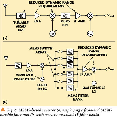
On the other hand, a number of proposals, predicated upon the top-down approach, have already appeared in literature,16,17 with particular emphasis on transceivers. For example, Larson has proposed two receiver concepts shown in Figure 8.16 One employs a MEMS-based tunable front-end filter aimed at improving integrability through the drastic lowering of the IF enabled by the filter. The other receiver employs an acoustic resonant IF filter bank aimed at simplifying system realization by eliminating the need for a tunable first LO, that is, by replacing it with a fixed LO and exploiting the switchable filter bank to affect IF band selection. Along the same lines, Nguyen proposed a front-end architecture,17 in which band selection is accomplished by the orchestrated action of a switched matching network and a massively parallel bank of MEMs filters shown in Figure 9.
|
|

Enabling The Next Wave:
Concurrent System Design
Without an appropriate environment, the design and timely implementation and time-to-market deployment of MEMS-based systems would be virtually hopeless, due to the design dimensions added by the multi-physics/multi-domain nature of MEMS devices. Thus, MEMS design tools are essential to the successful commercialization of MEMS-based RF/wireless systems.
CAD tools18 provide an environment where virtually all aspects of MEMS device design and production, from first principles physical simulation to system-level device models to packaging to manufacturing process feasibility, can be concurrently addressed to avoid last-minute surprises.
A typical design flow for an RF MEMS device is shown in Figure 10. From mechanical and electrical specifications, the device is designed iteratively19 until both sets of specifications are satisfied. Within the iteration loops, the software may be used to explore, and correct for, the impact of a number of potential influences on device performance/yield, such as package stress and strain state, manufacturing process or temperature variability, and hermeticity. The design process ends with an S-parameter file and/or a behavioral reduced order model for subsequent utilization in a circuit/system simulator.
|
|

CONCLUSION
In this two-part article, a succinct tutorial on the field of MEMS with particular emphasis on their ability to enable the breakthroughs that will launch the next class of RF/microwave wireless systems applications was presented. In Part I, MEMS-based RF devices, such as inductors, varactors, switches, resonators and transmission lines, their fabrication, packaging and a CAD design methodology, were progressively introduced. In Part II, some of their most important circuit and system applications, and possible approaches for their insertion, were described. In conclusion, the need for a concurrent system design environment, such as that provided by currently available software, was suggested, and a typical RF MEMS device design flow that could exploit such an environment was presented. *
References
1. H.J. De Los Santos, Introduction to Microelectromechanical (MEM) Microwave Systems, Artech House, Norwood, MA, 1999.
2. Asad A. Abidi, Fellow, IEEE, Gregory J. Pottie, Member, IEEE and William J. Kaiser, "Power-Conscious Design of Wireless Circuits and Systems," Proceedings of the IEEE, Vol. 88, No. 10, October 2000.
3. J.Y.-C. Chang, A.A. Abidi and M. Gaitan, "Large Suspended Inductors on Silicon and Their Use in a 2µm CMOS RF Amplifier," IEEE Electron Device Letters, Vol. 14, 1993, pp. 246248.
4. D.J. Young and B.E. Boser, "A Micromachined Variable Capacitor for Monolithic Low Noise VCOs," Solid-state Sensor and Actuator Workshop, Hilton Head, SC, June 26, 1996, pp. 8689.
5. Aleksander Dec and Ken Suyama, "Micromachined Electro-mechanically Tunable Capacitors and Their Applications to RF ICs," IEEE Transactions on Microwave Theory and Techniques, Vol. 46, No. 12, December 1998, p. 2587.
6. A. Dec and K. Suyama, "Microwave MEMS-based Voltage-controlled Oscillators," IEEE Transactions on Microwave Theory and Techniques, Vol. 48, No. 11, Part I, November 2000, pp. 19431949.
7. J.J. Yao and M.F. Chang, "A Surface Micromachined Miniature Switch for Telecommunications Applications with Signal Frequencies from DC up to 4 GHz," 8th Int. Conf. on Solid State Sensors and Actuators, and Eurosensors IX, 1995,
pp. 384387.
8. A. Malczewski, S. Eshelman, B. Pillans, J. Ehmke and C.L. Goldsmith, "X-band RF MEMS Phase Shifters for Phased Array Applications," IEEE Microwave and Guided Wave Letters, Vol. 9, No. 12, December 1999, pp. 517519.
9. Youngwoo Kwon, Changyul Cheon, Nyuntae Kim, Chungwoo Kim, Insang Song and Cimoo Song, "A Ka-band MMIC Oscillator Stabilized with a Micromachined Cavity," IEEE Microwave and Guided Wave Letters, Vol. 9, No. 9, September 1999,
pp. 360362.
10. K. Wang, Y. Yu, A.-C. Wong and C.T.-C. Nguyen, "VHF Free-beam High Q Micromechanical Resonators," 12th International IEEE Micro Electro Mechanical Systems Conference Technical Digest, Orlando, FL, January 1721, 1999, pp. 453458.
11. S. Cass, "Large Jobs for Little Devices," IEEE Spectrum, January 2001, pp. 7273.
12. F.D. Bannon III, J.R. Clark and C.T.-C. Nguyen, "High Frequency Microelectromechanical IF Filters," IEEE International Electron Devices Meeting Technical Digest, San Francisco, CA, December 811, 1996, pp. 773776.
13. C.T.-C. Nguyen, "Microelectromechanical Devices for Wireless Communications," 1998 IEEE International Micro Electro Mechanical Systems Workshop Proceedings, Heidelberg, Germany, January 2529, 1998, pp. 17.
14. Andrew R. Brown and Gabriel M. Rebeiz, "A High Performance Integrated Band Diplexer," IEEE Transactions on Microwave Theory and Techniques, Vol. 47, No. 8, August 1999, pp. 14771481.
15. J.W. Digby, C.E. Collins, B.M. Towlson, et al., "Integrated Micro-machined Antenna for 200 GHz Operation," IEEE MTT-S Digest.
16. L.E. Larson, "Microwave MEMS Technology for Next-generation Wireless Communications," 1999 IEEE MTT-S Digest.
17. C.T.-C. Nguyen, "Micromechanical Components for Miniaturized Low Power Communications," Proceedings of the 1999 IEEE MTT-S International Microwave Symposium RF MEMS Workshop (on Microelectromechanical Devices for RF Systems: Their Construction, Reliability and Application), Anaheim, CA, June 18, 1999, pp. 4877.
18. Computer-aided design software, Coventor Inc., 4001 Weston Parkway, Suite 200, Cary, NC 27513, USA.
19. H.J. De Los Santos, Y.-H. Kao, A.L. Caigoy and E.R. Ditmars, "Microwave and Mechanical Considerations in the Design of MEM Switches for Aerospace Applications," IEEE Aerospace Conference, Aspen, CO, February 18, 1997, Vol. 3,
pp. 235254.
Figure Attributions
Permission to reprint the figures in this article has been granted by IEEE. The specific manuscripts containing these images are listed here.
Figures 2a/b: J.Y.-C. Chang, A.A. Abidi and M. Gaitan, "Large Suspended Inductors on Silicon and Their Use in a 2 µm CMOS RF Amplifier," IEEE Electron Device Letters, Vol. 14, 1993, pp. 246248, Figure 2.
Figure 2c: J.Y.-C. Chang, A.A. Abidi and M. Gaitan, "Large Suspended Inductors on Silicon and Their Use in a 2 µm CMOS RF Amplifier," IEEE Electron Device Letters, Vol. 14, 1993, pp. 246248, Figure 4.
Figure 3: A. Malczewski, S. Eshelman, B. Pillans, J. Ehmke and C.L. Goldsmith, "X-band RF MEMS Phase Shifters for Phased Array Applications," IEEE Microwave Guided Wave Letters, Vol. 9, No. 12, December 1999, pp. 517519, Figure 2.
Figure 4a: Y. Kwon, C. Cheon, N. Kim, C. Kim, I. Song and C. Song, "A Ka-band MMIC Oscillator Stabilized with a Micromachined Cavity," IEEE Microwave and Guided Wave Letters, Vol. 9, No. 9, September 1999, pp. 360362, Figure 1.
Figure 4b: Y. Kwon, C. Cheon, N. Kim, C. Kim, I. Song and C. Song, "A Ka-band MMIC Oscillator Stabilized with a Micromachined Cavity," IEEE Microwave and Guided Wave Letters, Vol. 9, No. 9, September 1999, pp. 360362, Figure 2.
Figure 5a: F.D. Bannon III, J.R. Clark and C.T.-C. Nguyen, "High Frequency Microelectromechanical IF Filters," Technical Digest, IEEE International Electron Devices Meeting, San Francisco, CA, December 811, 1996, pp. 773776, Figure 1.
Figure 5b: F.D. Bannon III, J.R. Clark and C.T.-C. Nguyen, "High Frequency Microelectromechanical IF Filters," Technical Digest, IEEE International Electron Devices Meeting, San Francisco, CA, December 811, 1996, pp. 773776, Figure 2.
Figure 5c: C.T.-C. Nguyen, "Microelectromechanical Devices for Wireless Communications," Proceedings, 1998 IEEE International Microelectromechanical Systems Workshop, Heidelberg, Germany, January 2529, 1998, pp. 17, Figure 7.
Figures 6a/b: A.R. Brown and G.M. Rebeiz, "A High-performance Integrated-band Diplexer," IEEE Transactions on Microwave Theory and Techniques, Vol. 47, No. 8, August 1999, pp. 14771481, Figure 6.
Figure 6c: A.R. Brown and G.M. Rebeiz, "A High-performance Integrated-band Diplexer," IEEE Transactions on Microwave Theory and Techniques, Vol. 47, No. 8, August 1999, pp. 14771481, Figure 10.
Figure 6d: J.W. Digby, C.E. Collins, B.M. Towlson, et al., "Integrated Micro-machined Antenna for 200 GHz Operation," IEEE
MTT-S Digest, Figure 2.
Figure 8a: L.E. Larson, "Microwave MEMS Technology for Next-generation Wireless Communications Invited Paper," 1999 IEEE
MTT-S Digest, Figure 4.
Figure 8b: L.E. Larson, "Microwave MEMS Technology for Next-generation Wireless Communications Invited Paper," 1999 IEEE
MTT-S Digest, Figure 5.
Figure 9: C.T.-C. Nguyen, "Micromechanical Components for Miniaturized Low Power Communications," Pro. 1999 IEEE MTT-S International Microwave Symposium RF MEMS Workshop (on Microelectromechanical Devices for RF Systems: Their Construction, Reliability and Applications), Anaheim, CA, June 18, 1999, pp. 4877.