
 The omnipresent cell phone is a constant reminder of the wireless market explosion. The proliferation of cellular basestations is close behind, and this infrastructure is becoming more complex as evidenced by tall towers having several vertically co-located platforms, each with its threefold symmetry of antennas. As customer demand for connectivity continues to skyrocket, both cell sites and the electromagnetic spectrum feel the crunch for space.
Scarce real estate and the need to pack more channels under one cell-station roof mean more compact filter construction. Co-location of new services, such as the upcoming 3G and Universal Mobile Telecommunications System (UMTS), imposes requirements to isolate transmitters and receivers at the same or nearby sites. As a result, microwave filter manufacturers are poised for brisk business. But the classic filter design techniques pioneered in the 1960s and typified by Matthaei, Young and Jones1 may not fulfill today's requirements. Now, cross coupling for steeper filter skirts without introducing more resonators is commonplace. One of the most demanding goals is size reduction with minimal impact on performance, usually the retention of low filter insertion loss to maximize the microwave signal throughput and eventually the coverage provided by the cell site. Savvy microwave filter engineers have learned that modern ceramics can squeeze high performance into small spaces. In filter terms, high unloaded quality factor (Qu ) can be provided concurrently with high dielectric constant for size reduction.
But the filter(s) may not have the luxury of a benign environment, and could very possibly be tower-top located. Almost all materials used in microwave filters will change dimensions perceptibly with temperature, which can result in frequency drift of the filter's performance. Temperature compensation for minimal drift is an engineer's art. Ceramic compositions can be customer-blended for each application to minimize the drift. But ceramic filter resonators that behave linearly with temperature are a plus to the designer, for they may mean less resonators required to preserve filter stopband rejection as temperature varies.
Microwave filter design usually involves tradeoffs of performance, size and cost. High dielectric constant ceramics are popular where small filter size is a goal, and low insertion loss is necessary. However, using the highest Qu ceramics may be cost-prohibitive in high volume commercial applications, particularly for multi-pole filters. This is particularly the case for higher frequency applications, such as 1800 to 2500 MHz, where the highest Qu performance is achieved with the use of very expensive materials, such as tantalum pentoxide, as the primary base ingredient. The price of tantalum has increased by over 500 percent in the last year, with no signs of slowing down in the immediate future.
A new, non-tantalum-based ceramic material, D3500,® has been introduced, intended primarily for applications in low loss, multi-pole filters within the 1800 to 2500 MHz frequency range. With a nominal permittivity (dielectric constant) of 35, this material typically yields a Qu of 35,000 or more in a 80mm3 silver-plated cavity, in the TE01* mode. This performance is more than adequate for most applications and is achieved at a fraction of the tantalum-based ceramic price. This development will allow filter designers the choice to use a high Qu ceramic in their designs to achieve the desired performance.
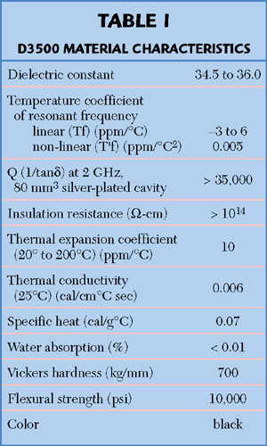
As shown by the performance parameters in Table 1, D3500 has been specifically designed as a resonator material for narrowband, multi-pole filters in the UMTS, PCS and DCS frequency bands. The range of nominal temperature coefficients (Tf) presented in the table indicates the standard available range. However, custom Tfs can be developed for specific applications by slightly modifying the material composition. Table 2 displays a range of possible material compositions with various nominal Tfs and respective dielectric constants.

The high linearity of the D3500 series material makes this an ideal candidate for harsh environments, where performance is required from 40° to +85° C without any external temperature compensation circuit. As shown in Figure 1, the high linearity component of temperature coefficient (T'f = 0.005ppm/°C2 ) results in a frequency drift of only 42 kHz over the temperature range of 40° to +25°C for a typical 2 GHz resonator.
|
|
|
As with all dielectric materials, the Q is highly dependent upon frequency of operation. As shown in Figure 2, the D3500 material displays excellent Q performance for applications under 2.5 GHz; however, it still maintains acceptable levels of Q for applications beyond 5 GHz. As listed in Table 3, higher Qs can be obtained with the D2900 series material at a much higher cost. The D3500 material provides excellent Q performance/cost tradeoff over other commercially available material, such as the D8300 and D4500 materials.

Once the filter designer has determined the desired performance, such as frequency range, tuning range and filter order, the available volume will dictate the range of sizes and shapes required of the ceramic dielectric resonator. The D3500 material begins as a proprietary technical powder that can be pressed, fired and machined into a variety of shapes and sizes to meet most demanding filter applications.
More and more filter designers are finding the benefits of low loss ceramics in their products. The D3500 material allows these designers to improve the filter's performance at minimal budget penalty. This alone will assist to promote the cost/performance tradeoff required for most 3G systems.
References
1. G. Matthaei, L. Young and E. Jones, Microwave Filters, Impedance-matching Networks and Coupling Structures, Artech House, Norwood, MA.
Trans-Tech Inc.,
a subsidiary of Alpha Industries, Adamstown, MD (301) 874-6540.
Circle No. 302