
High-resolution radars have a diverse set of uses in both commercial and military applications, ranging from automotive vehicle awareness to advanced target ID, surveillance and ballistic missile defense. These applications drive the need for wide instantaneous bandwidth radar. Understanding how a radar behaves in the frequency and time domain helps determine its overall performance, especially when dealing with short-duration pulses or the performance of frequency modulation on longer pulses.
Fundamentally, radar can be characterized as a time domain phenomenon. In its simplest form, it is the time it takes a transmitted signal to illuminate a target and “reflect back” to the receiver. The signal can be continuous wave (CW) or a sequence of pulses, depending on the specific mission. Pulse rise and fall times, the type of modulation and the behavior of the transmitter amplifier can create a range of responses in the frequency domain. The radar signal needs to be tested in congested—even contested—environments, and a key task is to verify immunity to signal interference, jamming and clutter effects.
Time domain measurements are traditionally performed with oscilloscopes, while spectrum analyzers are best suited for frequency domain measurements. However, advancements in measurement instrumentation architectures have shaken this up a bit. Now, broadband frequency domain analysis can be performed with an oscilloscope, and the time domain behavior of a frequency modulated signal can be analyzed using a spectrum analyzer. This article explores the trade-offs with each instrument.
RESOLUTION: TIME, MODULATION AND FREQUENCY
Radar resolution can be improved by using a very narrow pulse (in time); however, the amplification of short-duration pulses can be challenging, so techniques such as modulating a longer pulse with a frequency ramp, termed linear frequency modulation (LFM), are used. Frequency modulation does not necessarily have to be linear; in some cases, an exponential waveform may be better suited to a particular application.
Fast time domain events, such as radar pulses, exhibit sin(x)/x behavior in the frequency domain. If a pulse is short, the main lobe of the sin(x)/x function has a broader frequency response. If the pulse is wide, the lobe has a narrow frequency response. This affects the choice of transmission frequency: A short-duration pulse will require a large amount of spectrum, so a high carrier frequency should be used. Longer pulses require less spectrum and can be transmitted at lower frequencies. How often the pulse is repeated, termed the pulse repetition frequency (PRF), depends on the radar’s mission. Low PRFs are better for detecting targets greater than 50 km range, and high PRFs are better for closer targets. As a rule, a low PRF radar uses longer pulses and transmits at lower frequencies, such as in the VHF band, and high PRF radars use narrow pulses and transmit at higher frequencies.
When modulation is added, further frequency and time domain interactions are observed. For example, a 4 GHz bandwidth LFM chirp gives a resolution of around 6 cm, which is ideal for imaging applications. However, adding this type of modulation to a pulse will add ±2 GHz of FM modulation to the sin(x)/x frequency response, making a logical transmission frequency in the mid 30 GHz part of the spectrum.
TIME DOMAIN MEASUREMENTS
Traditionally, the oscilloscope has been the primary tool for examining varying voltage versus time. This is key to understanding pulse or pulse train behavior. Oscilloscopes are available with various levels of performance; a basic oscilloscope may have a bandwidth of 200 MHz, so it is a good tool for analyzing pulses with a frequency response less than 200 MHz, i.e., either unmodulated pulses or lower frequency pulses with slow modulation. However, the limited bandwidth of entry-level oscilloscopes means that degenerative effects such as intermodulation will be filtered out.
A modern, high performance oscilloscope can have bandwidths up to 70 GHz, providing the capability to capture multiple harmonics and other frequency-based distortion mechanisms. Without using a detector, oscilloscopes can capture and analyze the transmit frequency to help understand the behavior of both short-duration pulses, or impulses, and wideband signal modulation. For short-duration pulses and impulses, enhancements in architecture have improved the oscilloscope’s ability to analyze these signals using a fast acquisition mode. This reduces the dead time between waveform acquisitions, enabling the capture and display of transient events. Fast acquisition combined with persistent waveform features can display phenomena at varying intensity to reflect the rate of occurrence. Figure 1 shows a single pulse captured multiple times, with a persistence heat map technique used to show the rate of occurrence. Frequent occurrences are shown in red and infrequent events displayed in yellow to blue, for the most infrequent. The display identifies a number of intermittent pulses with lower amplitude and, occasionally, a pulse of shorter duration in blue. Figure 2 shows a string of “good” pulses with an occasional anomaly displayed in blue.
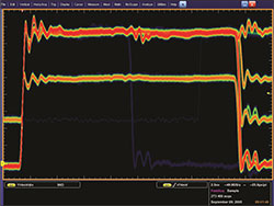
Figure 1 The fast acquisition mode can show a single, narrow pulse.
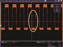
Figure 2 Discovery of a single transient glitch in a train of pulses.