
Editor's Note: Microwave Journal reached out to three leading test & measurement companies for contributions on the future challenges and solutions for radar sensor testing for automotive safety and autonomous driving applications.
The Future of Automotive Radar Testing with Modular Solutions
Matt Spexarth, National Instruments, Austin, Texas
Radar has multiple advantages over alternative sensing technologies, securing its role in automotive active safety and autonomous driving well into the future. Radar has the unique abilities to instantaneously detect the velocity of detected objects via the Doppler shift of their radar signatures, and to penetrate inclement weather conditions such as rain, fog and snow. These benefits are driving automakers to adopt radar in increasing numbers. In the U.S., the National Highway Traffic Safety Administration (NHTSA) reached an agreement with 20 automakers, representing more than 99 percent of the U.S. market, to voluntarily equip all production vehicles with Automatic Emergency Braking (AEB) by 2022, a safety feature often enabled by radar.
As vehicles evolve from Advanced Driver Assistance Systems (ADAS) to full autonomous driving, sensors such as radar, LIDAR and cameras are the critical input devices that enable the vehicle to accurately sense the environment around it, providing the context needed for the vehicle to make decisions. Future vehicles may include up to eight radar sensors to provide a full 360° surround view of the car.
Automotive Radar Test Evolution
The growth and advancement in automotive radar has led to several challenges for the test and validation of radar sensors. The first set of challenges center on meeting the increasing technical requirements for testing modern automotive radar while maintaining or lowering the cost of production test. It is typical for a modern radar sensor to require 1 GHz of bandwidth at 76 to 77 GHz and few companies have the expertise to build test systems in this frequency range. Higher bandwidth sensors provide finer resolution, and radar manufacturers have already demonstrated sensors with higher bandwidths approaching 4 GHz with a 79 GHz center frequency making the testing even more challenging.
While the technology in future radar sensors continues to improve, the time and cost of testing those sensors must be optimized to meet the price and volume requirements to enable the broad adoption of radar. Early radar sensor manufacturers used large anechoic RF chambers and corner reflectors to functionally test and calibrate modules. These chambers were commonly three or five meters long and consumed large amounts of manufacturing floor space. To reduce floor space, radar functional testing evolved to use analog delay lines to emulate long-distance radar obstacles followed by a second test station to perform parametric measurements of the radar.
Radar functional testing has evolved even further with dedicated systems such as the NI Vehicle Radar Test System (VRTS). The VRTS is a hybrid simulator built with a Vector Signal Transceiver (VST) which integrates an instrument-quality Vector Signal Analyzer with a Vector Signal Generator via a high-performance, low-latency FPGA (see Figure 1). This approach can consolidate a radar module production test cell by combining the functional test (object simulation) and the parametric tests into a single tester. The combination reduces manufacturing floor footprint and eliminates the overhead of transferring radar modules between test stations, improving throughput and freeing up space for additional testers.
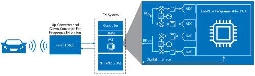
Figure 1 Block diagram of the NI Vehicle Radar Test System.
Beyond the higher frequency and bandwidth requirements of automotive radar testing, the next challenge of testing future radar sensors is the validation of increasingly complex software built into sensors. A radar sensor with 1 GHz or more of bandwidth produces massive amounts of raw data. To avoid overwhelming the communication buses and ECU of the vehicle, radar sensors include a processor to reduce this data into a summarized snapshot. Periodically, the radar transmits a parameterized object table with a summary of all the objects currently tracked by the sensor. Each object includes a range, velocity, radar cross section (RCS), object ID and confidence (a measure of the radar’s confidence that an object exists). The radar’s software detects these objects and tracks their real-time movements. Algorithms look for inconsistencies such as an obstacle that is moving away from the sensor but has a Doppler signature that indicates the obstacle is approaching.
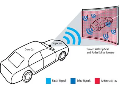
In the lab, engineers must validate these algorithms and the software that implements them. In-vehicle field testing of these algorithms is critical, but lab testing with a compact radar test system allows software developers to quickly validate software changes immediately. Combined with mechatronics to move the radar simulator antennas, systems like VRTS can generate standardized radar environments to characterize and validate radar sensor software, including simulating corner case scenarios that would be difficult or dangerous to emulate with drive testing. Lab testing with simulators is critical to maintaining the pace of innovation of automotive radar sensor design.
Within the context of the entire ADAS or autonomous driving system, engineers must also consider radar emulation for system validation test. Increasingly, these systems rely on a combination of sensors, including cameras, LIDAR and radar. Validating the overall performance of an ADAS function, like AEB, increasingly utilizes sensor fusion, the combination of two or more sensors to improve the quality or increase the confidence of obstacle detection. For example, if the ADAS radar sensors “sees” an obstacle but the cameras indicate the path is clear, then the ECU may disregard the radar obstacle as a ghost or interference.
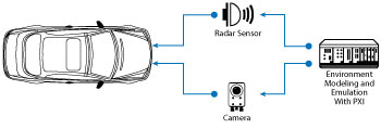
Figure 2 Validating the software for ADAS and autonomous driving requires synchronized emulation of multiple vehicle sensors so the vehicle “thinks” it is driving in the real world.
When testing these functions at the system level, engineers need a test platform that can support a wide set of synchronized sensor simulations to emulate the entire sensed environment around the vehicle. Because systems like VRTS are built on PXI-Express, the standard in modular, automated test equipment, engineers can support additional sensors by adding additional PXI modules, such as the NI FlexRIO, to emulate digital camera inputs in sync with the radar emulation (see Figure 2).
Finally, advanced radar modulation techniques will have an impact on the future of automotive radar testing. Frequency Modulated Continuous Wave (FMCW) radar has been the standard bearer for automotive radar. Radar designers are now looking to use MIMO antennas to augment automotive radar capability to accurately detect obstacle elevation or even provide a raster image similar to a camera. Radar sensor researchers are demonstrating higher performance based on modulation schemes that are similar to those that were commonly used in cellular communication. These schemes can channelize the frequency spectrum allocated to automotive radar, enabling MIMO radars to characterize individual radar reflections between parallel Tx and Rx paths.
This approach promises to improve radar resolution and field of view while enhancing the radar’s immunity to interference from other vehicles. In response, radar test systems must also grow in sophistication. Accurately emulating an obstacle at the resolution of these imaging radars may require demodulating individual radar channels, applying the obstacle effects of distance, Doppler and RCS for each Tx channel, modulating each channel per the original scheme and reflecting that obstacle back to the sensor—all at the roundtrip speed of light. These requirements will challenge radar test vendors and suppliers, requiring a high bandwidth, low-latency system architecture with extreme signal processing capabilities.