
Coupled Triplets
Albert J. Klappenberger and William B. Lurie
ALK Engineering
Salisbury, MD
As the state of the art in L-C filter design realization moves forward to satisfy the changing demands of today’s requirements, it appears that some of the more sophisticated techniques are giving way to older, less sophisticated techniques. At lower frequencies, the objective has been to reduce the total parts count, especially that of the inductors, to an absolute minimum. Today, the trend is toward the use of coupling between nonadjacent resonators (triplet and quad sections) to form finite attenuation peaks (stopband notches). This technique requires that the starting topology from which the cross-coupled topology will be formed be suited to that application. The development of experience toward this goal seems to be showing that the older, more complicated topology better provides the elements to support the transformations necessary for cross-coupled realizations.
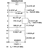 The two L-C filters described in this article are similar in performance in that both have three extreme zeros and two finite zeros at the same locations. The first, a coil-saving (or zigzag) filter, is the obvious choice as an L-C filter realization because it has one less inductor than the other. It is the result of exact synthesis. Of course, both filters will require transformations to achieve practical values before they can be built. However, the zigzag topology, shown in Figure 1 , does not lend itself to the conversion to cross-coupling when extended to higher orders without resorting to special methods during the synthesis to generate a topology more friendly to the final procedure.
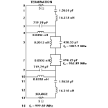 The filter shown in Figure 2 was designed by transforming a synthesized lowpass reference filter1 into a bandpass configuration.2 The series L-C sections resonant at geometric f0 that appear at each end of this particular filter are the key to developing realizable filters of higher order. When transformed to a bandpass configuration, a lowpass reference having a single series inductor between each series L-C trap (finite zero) will generate pairs of finite zeros located on opposite sides of the passband and separated by these series L-C networks. These L-C networks provide the elements needed to apply Norton transforms to effect an impedance transition from one set of triplet sections to the next. The zigzag topology3 of the first filter will leave the designer with no way to adjust the impedance of the following set of finite zeros in a higher order filter.
 Ultimately, a bandpass filter could be designed to have the same topology as one resulting from lowpass transformation by exact synthesis.4 This procedure will allow complete freedom to place the finite zeros at any desired point rather than the geometric symmetry yielded by lowpass-to-bandpass transformation.
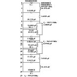
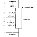
Figure 3 shows the second filter transformed to use triplet sections having one-quarter-wavelength coaxial ceramic resonators for increased Q for the finite zeros.5 Similarly, resonators of any impedance using any desired dielectric material could be used. The other parallel resonant L-C networks also may be replaced by shorted stubs, but that topic is beyond the scope of this article. It should also be noted here that the 5 W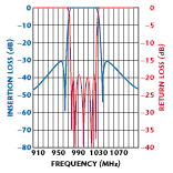 impedance level at the source and termination of these examples is for comparison only. Additional transformations, such as narrowband matching, will be needed to achieve 50 W. Appendix A shows the Touchstone® network listing for this filter; Figure 4 shows a computer simulation of the filter’s response. Unfortunately, measured data are not available to verify this performance.
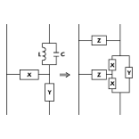 At the heart of this transformation is the set of equivalent network tri-plets, shown in Figure 5 . In the original network on the left, X may be L or C and Y may be L or C, but X and Y must be of opposite types. In the triplet form on the right, Y will be of the same type as Y in the left network. Each of the X elements on the right will be L or C independently, depending on the element values in the notch. Element Z on the right will be of the same type as X on the left. The case shown in Figure 6 involving shunt notches can be considered trivial in that the triplet can be derived from simple delta-to-tee equivalences.6 The notch elements themselves are simple dipole equivalents.
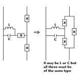 During the course of transformations, networks of the type shown in Figure 7 , which involve a shunt L-C pair with a series element on one side and a series trap on the other, occur very frequently. The additional shunt element of the same type as the single series element first must be removed to make the network topology conform to that shown in Figure 5 . In some cases, a simple delta-to-tee transformation involving the single series element, branch 2, and the adjacent shunt elements that might exist at branches 1 and 3 will remove the unwanted element. The unwanted parallel element also can be removed by applying Norton’s transformation7 with the impedance ratio chosen to force the value of the unwanted element to that of an open element, that is, a 0 pF capacitor or a huge value inductor as the case may be. The transformation would involve the elements at branches 1, 2 and 3.
 When the Norton transform method is employed, an opportunity exists to actually choose an impedance transformation ratio that may be used to scale the entire network from the triplet to the termination. This procedure may be accomplished by first applying a Norton transform involving the series notch and one of the parallel elements (that is, branches 5 and 3 or 4). The product of this impedance ratio and the one chosen to remove the unwanted element becomes the overall scaling ratio. This ratio may be specified as 1.0 if desired.
Note that even though an L-C resonator is shown in the resulting triplet, one of the elements will be of open value. This configuration is in keeping with the single parallel component of the triplet shown in Figure 5 . It is there only to provide the topology needed to scale the impedance of the resonator.
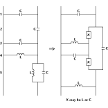
 Once the triplet has been formed, it becomes very simple to force the values forming the internal resonator consisting of branches 22 and 23, shown in Figure 8 , to any values needed as long as the impedance at the points where the bridging element is connected does not change. The impedance of the resonator may be adjusted by performing two Norton transforms7 involving the p configuration of elements on either side of the resonator. The transformation ratios simply must be reciprocals.
The true advantage of the triplet topology as applied to the L-C filters is the ability to substitute a transmission line resonator in place of the L-C resonator within the triplet. This transmission line resonator would take the form of a shorted stub made from microstrip, coaxial air line or a ceramic dielectric resonator. The mathematical expression for the impedance of a shorted stub as a function of frequency and its dimensions is well known.8
For use in a filter, the stub must be as accurate a substitute for the L-C network as can be conveniently realized. The most important frequencies for each section of the filter are somewhere in its passband and the frequency at which that section creates a transmission zero. It was decided to determine the impedance of the L-C resonator at the filter geometric center frequency and at the section’s transmission zero frequency and find a stub that matches the L-C it replaces at those two frequencies. In a narrowband case such as this, the decision to use the center and stopband frequencies rather than the passband corners is justifiable.
Formulas for the determination of the stub’s characteristic impedance and length do not exist explicitly, but the procedure to determine them is relatively straightforward. One obvious method is by iteration. A Newton’s method root finder has proven to be an effective method when the necessary values are subtracted from the results of the impedance equation. Once the procedures are in place to adjust the impedance at the top of the resonator and accurately replace the L-C network with a shorted stub, iterations can be used to force any values of L, C or stub impedance needed as a totally independent step after all other transformations are complete.
Acknowledgment
Thanks and recognition are extended to George Szentirmai for the mathematical derivation of the equivalent networks used here and for permission to use the triplet equivalents in the PCFILT program.
References
1. Saal and Ulbrich, “On the Design of Filters by Synthesis,” Reprinted in Computer-aided Filter Design , IEEE Press, Edited by George Szentirmai, Figure 3, page 41.
2. Saal and Ulbrich, “On the Design of Filters by Synthesis,” Reprinted in Computer-aided Filter Design , IEEE Press, Edited by George Szentirmai, Figure 11, page 52.
3. Saal and Ulbrich, “On the Design of Filters by Synthesis,” Reprinted in Computer-aided Filter Design , IEEE Press, Edited by George Szentirmai, Figure 12, page 53.
4. G. Szentirmai, “FILSYN: A General Purpose Filter Synthesis Program,” Proceedings of the IEEE , Vol. 65, October 1977, pp. 1443-1458. (ALK Engineering Web site: http://www.web-span.com/alk )
5. PCFILT User’s Guide , Appendix D. (ALK Engineering Web site: http://www.web-span.com/alk/ )
6. Anatol I. Zverev, Handbook of Filter Synthesis , Section 10.2, Figure 10.4, page 529.
7. Anatol I. Zverev, Handbook of Filter Synthesis , Section 10.4, page 530.
8. Reference Data for Radio Engineers , Fourth Edition, Page 561.
Albert J. Klappenberger has been promoted from bench technician to lumped component product line engineer at K&L Microwave. As the principal author of the PCFILT filter design program, he also has considerable experience in the application of theoretical designs to the requirements of lumped component filter designs commonly used in production hardware and the development of related computer software. Klappenberger’s principal area of expertise is lumped component filter and multiplexer designs in the 100 to 2000 MHz frequency range.
William B. Lurie gained experience in numerous fields of mathematics, physics and electronics from 1941 to 1961 before specializing in filters. From 1961 to 1969, he was chief engineer for the largest US independent lumped-constant filter manufacturer. Since then, he has been an independent consultant on filters. Lurie has published articles and papers dating from 1948 to 1994.
APPENDIX A
Touchstone circuit list
The Touchstone network listing for the example bandpass filter:
|
DIM |
|
|
|
IND NH |
|
CKT |
|
|
|
! - Termination Zo = 5 Ohms - Branch 0 |
|
TERM |
|
|
|
CHAN1 -8.181818e-01 0 -8.181818e-01 0 |
|
OUT |
|
|
|
CHAN1 DB [S21] GR1 |
|
FREQ |
|
|
|
SWEEP 900.884 1108.27 0.92583 |
|
GRID |
|
|
|
RANGE 900.9 1108.3 20.7 |