
In the last decade, automotive sensor systems emerged as the largest single market for compact radar systems. Standardization of frequencies and the economics of chip-scale production made the technology practical in mid-range and long-range sensor applications, resulting in market adoption at a pace approaching annual volume of tens of millions of chipsets. Now, recently developed single-chip radar that meets size and performance thresholds needed for a much wider range of consumer electronics devices is set to trigger an exponential increase in the use of radar.
A key driver for this growth is the rapid evolution of the Internet of Things (IoT). By the end of this decade, we will be surrounded by IoT devices. Many will be sensors that operate with no human intervention. Yet many others will be designed for interaction with users. These new types of devices, beginning with wearables, require a new type of user interaction. One of the most exciting new interaction methods is gesture control.
For wearable electronics, such as smartwatches, use of conventional physical controls and/or interaction on a tiny screen interface is a detriment to the user experience. Precise control of tiny devices using even a simple graphic interface or set of physical controls is difficult to achieve without dedicating a large part of the available surface of the device to the interface. Interaction is increasingly challenging as devices get smaller in size and the available real estate for a touch display screen shrinks.
Figure 1 Touch interaction challenges vary with screen size. Source: From Soli Team at Google ATAP.
As shown in Figure 1, researchers at Google’s Advanced Technology and Projects (ATAP) Group demonstrated that the load on the human motor control system increases exponentially when screen sizes smaller than 2"× 2". As a result, gestures are becoming relevant to human-machine interaction as a replacement or addition to touch screens and voice control. A gesture interface is very well suited to wearable electronics with limited real estate for controls. It also allows control in high ambient noise environments where voice may be ineffective. When the scope of applications is expanded from wearables to the types of ‘invisible’ sense and control systems envisioned for the IoT, the value of a gesture-based interface is amplified.
The technologies available to implement gesture control include capacitive, visible and infrared light, ultrasonic and radar. While each is useful for specific applications, radar-based human-machine interaction may prove to be the most flexible and widely deployed. Capacitive sensing is short range, while light and sound-based sensors are sensitive to environmental conditions like noise, rain, wind and temperature changes. These types of sensors also cannot be mounted invisibly and tend to introduce constraints for the industrial design of the end product. Finally, each of these alternatives has limited flexibility in terms of directional capability and distance measurement.
Millimeter wave (mmWave) radar’s capabilities as a sensor for gesture control applications overcome these limitations. It can operate in all lighting conditions, can transmit through many materials (e.g., polycarbonate) and is resistant to moisture, dirt and temperature variations that limit infrared, ultrasonic and laser-based sensor systems.
When compared to microwave frequency bands, a V-Band (57 to 64 GHz) sensor has several additional advantages. One of them is the range resolution, i.e., the ability of the radar sensor to distinguish two closely spaced targets as separate targets. There is 7 GHz bandwidth available in the unlicensed V-Band, which theoretically results in range resolution of 2 cm.
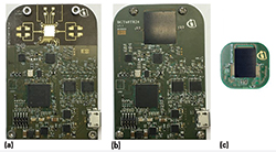
Figure 2 Infineon reference designs for different BGT60TR24: first generation with bare die (a) second generation in a 14 mm × 14 mm2 package (b) third generation in a smaller 9 mm × 12.5 mm2 package (c).
This can be extended to sub-millimeter scale resolution using advanced signal processing techniques. At mmWave frequencies the wavelength (5 mm at 60 GHz) is small enough to allow easy integration of multiple antennas in a package. A mmWave sensor also has better Doppler sensitivity, as the Doppler shift caused by a moving object is proportional to the operating frequency of the sensor. In the 57 to 64 GHz band, the corresponding Doppler shift is comparatively easier to detect and process than microwave bands. This eases detection of slow moving objects. Another advantage of a mmWave sensor is that the path loss at these frequencies is very high (1m = 68 dB @ 60 GHz). As the signal suffers large attenuation, it does not cause interference with other systems operating nearby.
The combined advantages of mmWave technology led the Google ATAP researchers to partner with Infineon on a project to engineer a radar sensing system with the size, power consumption and resolution needed for gesture control applications in consumer electronics products. The combination of Infineon’s two decades of experience in high-frequency RF technology and the cross-functional expertise at ATAP contributed to a remarkably fast development process for the Alpha DevKit.
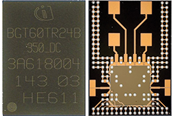
Figure 3 Infineon’s Soli chipset BGT60TR24B (top and bottom views).
FROM CONCEPT TO SINGLE-CHIP
Beginning with a benchtop concept in July 2014, a collaborative engineering team developed a series of hardware prototypes, iterating through designs using off-the-shelf, multi-chip radar components and ultimately producing a proof of concept IC. Demonstrated for the first time in May 2015, this single-chip radar and associated system components were released on a limited basis as the Soli Alpha Development Kit to developers for concept application development.
In the Soli Alpha development kit, the Soli radar chipset is paired with Google-developed algorithms for signal processing and a gesture library for developers that runs on an application processor. The sensor software abstracts signals in real-time and analyzes the signals at up to 10,000 fps to precisely determine position and motion and ultimately recognize gestures. Most of the gestures are designed so that haptic feedback is provided by the sensation of fingers moving against each other, which makes each gesture feel natural and responsive. The sensitivity of the Soli radar allows recognition of overlapping fingers and gestures in a 3D space. The radar has sub-millimeter resolution allowing the recognition of a range of gestures from large sweeping hand motions to micro gestures. This common language helps developers to quickly implement system designs and will let users learn to interact with Soli-powered devices in an easy-to-learn and consistent way.
The device still required a stand-alone PC to process the data gathered by the sensor and drew 1.2 W in operating mode. Also this early iteration of the device was a bare-die that required special PCB material to have low losses at 60 GHz, involved a lot of design effort for the on-board antennas, required wire-bonding for assembly and had a larger form factor. So the team continued its work to reduce power requirements and size while enhancing system integration, as shown in Figure 2.
Figure 4 BGT60TR24B block diagram.
The result of this effort is integrating Soli, a new sensing technology, into one of the world’s smallest radars to detect touchless gesture interactions. The chip, shown in Figure 3, and its corresponding software suite bring precise gesture control capability to consumer electronic products. Fabricated in Infineon’s BiCMOS process, the highly integrated chipset contains the complete RF front-end, baseband and ADCs, as well as memory, state machine and a programmable serial interface for communication with any application processor, as shown in Figure 4. The high level of integration, small form factor and overall efficiency of the BGT60TR24B ensure that it can fit into space constrained devices, for example a wearable band.
BGT60TR24B has effective isotropic radiated power (EIRP) of up to 10 dBm. The output power level can be varied by the integrated VGA in the transmit chain. As per the FCC rules, 10 dBm EIRP is the maximum allowable power limit for a field disturbance sensor covering the 57 to 64 GHz bandwidth. Recently the FCC1 also made amendments to Section 15.255 of its rules that would allow for the field disturbance sensors to operate over an even wider bandwidth (57 to 71 GHz).
Phase noise of the integrated VCO has a major impact on the sensing system. In a Frequency Modulated Continuous Wave (FMCW) system the targets are detected at a certain offset from the carrier frequency. As the received signal level from a far-off target has low level, it could be masked by the phase noise of the carrier and may not be detected. This is more likely if the target is far away and has low radar cross section, such as a human body or hand. With its phase noise of -80 dBc/Hz @ 100 kHz offset, the Soli radar chip improves the system SNR to allow detection of farther away targets.
In FMCW systems, the range to the target is proportional to the difference in frequency between the received and emitted signal, which is referred to as the beat frequency. This is typically a couple of MHz depending on modulation parameters and target range. The lower flicker noise corner of BGT60TR24B ensures that the beat frequencies from the target of interest are not degraded by the flicker noise.
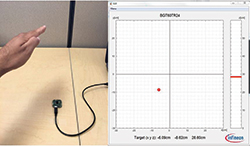
Figure 5 GUI view showing the location of the hand in XYZ coordinates.
The single chip radar also can easily interface via standard SPI to the existing processor inside the device. The fast SPI of the sensor enables raw data from the sensor to be fed to the signal processing pipeline running on the processor at the very high frame rate necessary for the end application to achieve real time-like performance.
The BGT60TR24B is housed in an embedded Wafer Level Ball (eWLB) Grid array package with ball pitch of 500 µm and can be mounted on a standard low cost FR4 PCB. The packaged IC has dimensions of 9 mm × 12.5 mm × 0.8 mm. It has two transmit channels; four receive channels and corresponding antennas to detect objects and motions up to 10 m distant. The four RX antennas are placed in 2×2 array to minimize grating lobes. The RX channels can be used to implement digital beam forming for tracking the objects in both the azimuth and elevation planes. The chip is designed with the flexibility to enable and disable several integrated blocks. For example, in application scenarios where only one receive channel is sufficient to detect a target the others can be turned off in order to extend battery life of the device.
The chipset also has an idle mode in which most of the integrated blocks are switched off. This mode is especially useful in cases when the sensing application running on the device is not used frequently. The complete radar system uses a 1.8 V power supply and draws 0.054 W in sensing mode. This low power consumption and thermal dissipation makes the integration of radar sensors into wearable devices practical, while assuring a comfortable end-user experience of the device. In addition to wearables, the integration and flexibility of the solution allows for cost effective implementation in a wide range of applications like gaming, virtual reality and mobile devices.
Figure 6 Typical implementation of a BGT60TR24B-based sensing system.
OPERATING PRINCIPLES
Infineon produced its first single-chip radar system, a 24 GHz device integrating a single transmit and two receive channels in a 4.5 mm × 5.5 mm footprint, in early 20142. The Soli chip applies this experience in a higher frequency, high bandwidth, high integration and low power consumption device, and the underlying signal processing and analysis algorithms are tightly linked to the unique characteristics of the hardware.
Antenna design, in particular, plays an important role for effective transmit and receive when the entire array is contained within the confines of the 9 mm × 12.5 mm × 0.8 mm package. The antennas integrated in package cover the complete 57 to 64 GHz bandwidth in order to achieve higher range resolution. The 2×2 RX antennas have gain of 10 dBi and half power beam width (HPBW) is 42º × 45º (E- and H- Plane). The TX antennas have gain of approximately 5 dBi and HPBW is 90º × 65º.
The wider beam width of the transmit antennas ensure that the entire scene in front of the sensor is captured for the signal processing pipeline. The spatial arrangement of two transmit and four receive antennas allows the sensor to precisely scan a 3D area in its field of view. As an example Figure 5 shows a GUI which displays the position of hand in front of sensor in XYZ coordinates. Also, the integration of all antennas in the package makes it easier for developers to design a low-cost PCB as there is no need to route 60 GHz signals on the PCB.
Figure 7 FMCW ramp generation using an external PLL and digital data capture with the processor.
A typical sensor system implementation comprises the blocks shown in Figure 6.
The BGT60TR24B radar chipset handles the RF signals and provides the digitized data to the processor via a digital interface; the application processor gets digitized data from the sensor, processes it and then runs the user application; the PLL locks the carrier of the BGT60TR24B to provide a highly linear FMCW modulated signal; the reference oscillator provides the clock to the chipset and the PLL; and the power management IC provides the required supply voltages to different blocks.
The BGT60TR24B sensor transmits a FMCW signal from 57 to 64 GHz on one of the transmit channels. In order to obtain highly accurate range and velocity information from the target it is required that the FMCW ramp has high linearity over the complete frequency sweep. If this is not the case the beat frequency corresponding to the target will drift, resulting in reduced accuracy of the measurements. On the system evaluation board, a highly linear FMCW sweep is generated by locking the carrier with an external PLL. The BGT60TR24B has an internal divide-by-16-circuit that provides a low frequency (4 GHz @ 64 GHz) signal at its divider output to connect to the external PLL. The transmitted FMCW signal hits the target and a part of it is reflected back to the four receiving antennas of the BGT60TR24B as shown in Figure 7.
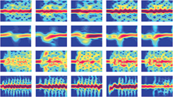
Figure 8 Sensor data showing four gestures by five users. Source: From Soli Team at Google ATAP.
The receive channels down-convert the reflected signals to the IF frequency. The frequency of the IF signal corresponds to the distance of the target from the sensor and the modulation parameters, i.e., bandwidth of the transmitted signal and ramp duration of the FMCW chirp. The IF signal passes through filtering and baseband amplification stages in order to have sufficient drive level for the following ADC stage. The gain of the baseband stages can be controlled via the digital interface. The frequency of the IF signal can vary up to MHz range, so the baseband filtering and the ADC sampling rate needs to be adjusted for the application of interest.
The ADCs digitize the IF signal at the set sampling rate and the resulting data is stored in the internal memory of the chipset. The memory is accessed by the external application processor via the digital interface. The application processor is the master controller, which triggers the FMCW ramp and ADC sampling and then captures the raw data when it is available in the memory of the sensor. The amplitude, frequency and phase of the reflected signal contain information about the size, distance, velocity, direction of movement and angular location of the target with respect to the sensor. The application processor runs software and algorithms to extract all target information by analyzing changes in the received signal over time. Based on variations in temporal signal, the system is able to differentiate both deformation in hand shapes and complex finger movements, which are incorporated into a control gesture library.
The gesture recognition pipeline abstracts data from the raw signal through proprietary transformations to determine position and motion data for analysis by image and gesture recognition libraries. A sample of typical data is shown in Figure 8. Most of the defined gestures generate a haptic sensation as a result of finger touch which is a clear advantage over gesture sensing systems like cameras. The consideration of haptic feedback while defining the gesture library results in both the fluidity and precision of natural motions.
In addition to efficacy of the sensor system, the unplugged nature of wearables and many potential IoT applications makes low power operation critical for the single chip radar. Every functional block of the IC is designed to power down outside of its specific duty cycle. Wake-up and duty cycles are user-controlled to provide maximum flexibility; a wearable might be designed to trigger a radar wake-up based on arm motion detected by a positional sensor. Other wake-up scenarios are likely for in-wall or tabletop devices.

Figure 9 Future human-machine interaction enabled by gesture sensing technology.
PROJECT STATUS
Google’s demonstrations of Project Soli at the Google I/O Conference in May 2016, included a smartwatch prototype that was operated with precise, close range finger gestures and a wireless speaker prototype controlled from several meters distance using hand gestures. These are expected to be the first in a wave of consumer products that can be precisely operated using hand movements only. Home appliances, smart home systems, and VR headsets controlled by hand motion are other systems that benefit from gesture control. And these are just a starting point, as developers working with the early development version of the system have demonstrated applications in object recognition, 3D imaging, security, advanced visualization and music. Google will release developer kits based on this radar-on-a-chip IC, with chip production to follow.
Effortless, intuitive gesture control frees product designers from the constraints imposed by buttons, switches and small screen display technologies. It truly represents a new paradigm in user interface design. Whether used to control IoT devices or as a way to navigate in augmented reality applications, like the scenario illustrated in Figure 9, radar-based gesture control clearly is a defining technology for man-machine interaction in the 21st century.
ACKNOWLEDGMENT
The authors would like to thank the Soli team at Google ATAP and Soli team at Infineon for the continued collaboration.
References
1. FCC, Report and Order and Further Notice of Rulemaking, July 14, 2016, http://transition.fcc.gov/Daily_Releases/Daily_Business/2016/db0728/FCC-16-89A1.pdf.
2. Microwave Journal, “Single-Chip 24 GHz Radar Front-End,” February 13, 2014, www.microwavejournal.comarticles/21553-single-chip-24-ghz-radar-front-end.