
A compact second-order microstrip bandpass filter with good frequency selectivity and a wide stopband consists of two dissimilar half-wavelength stepped impedance resonators (SIR) with centrally-embedded bandstop resonators. By adding one short-circuited stub, wideband spurious suppression is realized. Design and synthesis procedures are provided. Measurement is in good agreement with simulation. It exhibits a fractional bandwidth of 7.7 percent at 2.07 GHz with 17.4 dB of suppression from 2.25 up to 20 GHz. The size of the filter is only 0.19 × 0.19 λg (where λg is the guide wavelength at center frequency) without the use of any lumped elements.
Figure 1 Filter layout.
Microstrip bandpass filters (BPF) with low insertion loss, compact size, high frequency selectivity and a wide stopband are essential components in the design of receivers and transmitters for microwave and wireless communication systems; however, they often suffer from spurious responses at multiples of their fundamental frequencies. Various methods have been proposed to suppress these responses. A compact, wide stopband, bandpass filter realized by bending the resonators to suppress harmonics was proposed by Hsu and Tu,1 but only the second- and third-order harmonics were eliminated. Kuo et al.,2 obtained a wide stopband using both stepped-impedance resonators and bandstop structures. With the assistance of two spur lines, the stopband performance was further improved.3 By properly arranging the spurious harmonic frequencies of each resonator with an embedded transformed radial stub (TRS), an ultra-wide stopband with deep rejection has been realized.4 Wu et al.,5 developed a BPF consisting of two half-wavelength resonators loaded with two short-circuited stubs at both central planes, in order to provide more transmission zeros in the stopband. A zero-degree feed structure incorporated into the design of the microstrip filter added two transmission zeros, improving frequency selectivity.6
Figure 2 Simulated frequency response of the filter with dissimilar SIRs.
This article describes a compact second-order BPF with good frequency selectivity and a wide stopband. It is composed of two dissimilar half-wavelength SIRs with a bandstop resonator embedded into each SIR central plane. The bandstop resonators have different frequency ranges and one of them is loaded with a short-circuited stub to eliminate undesired spurious.
FILTER DESIGN
The filter layout is shown in Figure 1 with dimensions (in mm and degrees): r1 = 9.1, r2 = 5, r3 = 10, r4 = 7.45, d1 = 0.34, d2 = 0.8, m1 = 0.9, m2 = 3.2, m3 = 1, m4 = 0.25, m5 = 1, m6 = 2.45, l1 = 0.6, l2 = 1.4 , l3 = 1.36, l4 = 0.5, l5 = 4.5, Φ1 = 0.5, Φ2 = 1, deg1 = 42, deg2 = 5, deg3 = 22, deg4 = 5, deg5 = 5 and deg6 = 30. Both the input and output impedances of the feed structure are 50 Ω.
The second-order filter is designed using coupled-resonator procedures.7 The design parameters are determined for a Chebyshev response with a center frequency of 2.02 GHz, return loss of about 20 dB and a fractional bandwidth of 7.7 percent. The associated external quality factor and coupling coefficients are
Figure 3 Single microstrip bandstop structure (a) with simulated responses of bandstop resonator (b) and slot-loaded bandstop resonator (c).
where g0, g1 and g2 are the element values of the lowpass prototype filter, and FBW is the fractional bandwidth. EM simulation software is employed to establish the required design curves for external quality factor and coupling coefficients and to determine the physical dimensions. The SIRs and bandstop resonators are well characterized and their frequency responses evaluated and adjusted. To analyze the performance of the BPF, frequency responses of each structure are studied separately.
As shown in Figure 2, the filter exhibits two transmission zeros close to the passband, formed by a zero-degree feed structure.6 The transmission zeros significantly improve frequency selectivity. By properly arranging the impedance ratio and length ratio of each SIR, both of which have the same fundamental resonant frequency but different spurious (harmonic) resonance frequencies, several higher-order spurious frequency bands are suppressed. Moving the right SIR up vertically by d2 is another way to suppress spurious frequency bands. It reduces the coupling between higher-order spurious resonances, while coupling between the fundamental resonances remains unchanged. The SIRs are also used to push spurious harmonics to a higher frequency region. As a result, stopband characteristics are improved in the lower stopband but worsen in the higher stopband. The SIR structure exhibits a slow-wave characteristic to reduce the circuit size.
Figure 3a shows the physical layout of one microstrip bandstop resonator structure, which consists of a coupling section and a shunt open-circuited resonator. Its dimensions (in mm) are: a1 = 4.72, b1 = 5.79, c1 = 5.32, e1 = 0.33, g1 = 0.14, g2 = 0.2, w1 = 5 and w2 = 0.7. To widen the upper stopband, a slot line is embedded into the shunt open-circuited resonator. Shown in Figure 3b, this bandstop structure is modified from Hsieh and Wang.8 They reported that the coupling section and shunt open-circuited resonator are a quarter guided-wavelength long at the center frequency. In this work, the lengths of the coupling section and shunt open-circuited resonator are not fixed at quarter guided-wavelength, allowing greater design freedom in locating the transmission zeros to achieve a wider stopband and provide higher rejection. This structure exhibits a stopband from 4.2 to 13.4 GHz with rejection better than 10 dB (see Figure 3b). Figure 3c shows the simulated frequency response of a slot-loaded bandstop resonator where another transmission zero, determined by the slot line dimensions, is used to extend the stopband to 15.6 GHz. A bandstop embedded resonator (BER) is formed by embedding the bandstop structure into the center of the SIR. This structure can be tuned to suppress the lower spurious SIR harmonics.
To extend the stopband, another slot-loaded bandstop resonator with a higher frequency response is introduced (see Figure 4). Figure 4a shows the physical layout with dimensions (in mm): a2 = 3.9, b2 = 4.4, c2 = 3.9, e2 = 0.45, g3 = 0.4, g4 = 0.2, w3 = 4 and w4 = 1. Figure 4b shows the simulated frequency response. It exhibits better than 10 dB rejection from 7 to 20 GHz. With this structure to suppress the higher SIR spurious harmonics, one may implement a compact BPF with a widely extended stopband.
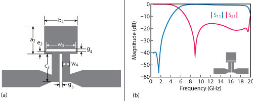
Figure 4 Second microstrip bandstop structure (a) with simulated frequency response (b).
The circuit configuration and performance of the second-order microstrip filter is shown in Figure 5. Two variable-sized slot-loaded bandstop resonators are embedded into the SIRs at both central planes. Theseare key to broadening the stopband and making the circuit compact. By properly arranging the bandstop structures, the center frequency (f0) of the filter is reduced with no insertion loss degradation in the passband. To analyze stopband performance, f0 is set to 2.02 GHz (the same value shown in Figures 2 and 5). Since the structure of each BER in Figure 5 is symmetrical, odd- and even-mode analysis can be adopted. For odd-mode excitation, there is a voltage null along the symmetrical plane of each BER. The signal to the shunt open-circuited resonators in the bandstop structures is shorted to ground and the odd harmonics have a low degree of suppression, about 13.08 dB. If the symmetrical plane of each BER is replaced with a magnetic wall for even-mode excitation, the even harmonics are eliminated effectively by the bandstop structures. The first even-mode spurious passband (with about 11.32 dB suppression), however, occurs at 2.85 GHz because the frequency is not in the stopband range of the bandstop resonators. By attaching a short-circuited stub to the left BER while keeping the right BER unchanged (see Figure 1), symmetry of the left BER is destroyed, and this disturbs the even- and odd-mode excitations. Some harmonics of the left BER are shorted to ground through the via-hole, thus eliminating undesired responses. The effect of the stub on the passband frequency response can be ignored. The simulated microstrip bandpass filter frequency response in Figure 6 shows that the spurious frequencies of the upper stopband are suppressed by greater than 19.8 dB from 2.23 to 20 GHz.
Figure 5 Simulated frequency response of the filter with SIRs and slot-loaded bandstop resonators.
Figure 6 Simulated frequency response of the proposed filter with SIRs, slot-loaded bandstop resonators and a short-circuited stub.
EXPERIMENTAL RESULTS
The BPF (see Figure 7) was fabricated on Rogers 5880 substrate, with dielectric constant, loss tangent and thickness of 2.2, 0.0009 and 0.76 mm, respectively. Simulation was performed with ANSYS HFSS 15.0 EM simulation software, and performance was measured with an Agilent N5244A network analyzer. Figure 8 shows simulated and measured S-parameters of the second-order BPF. The measured center frequency was 2.07 GHz, which was shifted up by 50 MHz compared with the simulation (see Figure 8a). This is attributed to tolerances in fabrication and assembly. Measured minimum insertion loss and 3 dB fractional bandwidth in the passband were about 1.39 dB and 7.7 percent, respectively. A passband return loss greater than 23 dB was also achieved. Two transmission zeros, located at 1.82 GHz and 2.41 GHz, improve frequency selectivity. Spurious harmonics were suppressed by greater than 17.4 dB from 2.25 to 20 GHz.
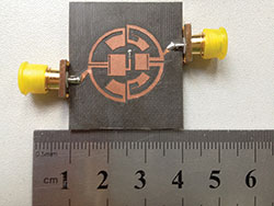
Figure 7 Fabricated bandpass filter.
By leveraging the intrinsic characteristics of SIRs and bandstop centrally embedded resonators, and with the assistance of one short-circuited stub, an effective second-order BPF with good passband performance and a wide stopband has been demonstrated. The filter design achieved an ultra-wide stopband (greater than 10 times the fundamental operating frequency), low insertion loss, good frequency selectivity and compact size. The circuit’s area was only 0.19 × 0.19 λg, where λg is the guided wavelength at 2.07 GHz. These features make it attractive for use in modern wireless communication systems.
This work was supported by the National Natural Science Foundation of China (grant 61001012).
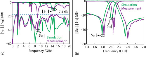
Figure 8 Simulated vs. measured filter response from DC to 20 GHz (a) and 1.4 to 2.8 GHz (b).
References
- K.W. Hsu and W.H. Tu, “Design of a Compact Wide-Stopband Bandpass Filter Using Meandering Uniform-Impedance Resonators,” Asia Pacific Microwave Conference, December 2009, pp. 2522]2525.
- T.N. Kuo, W.C. Li, C.H. Wang and C.H. Chen, “Wide Stopband Microstrip Bandpass Filters Using Quarter-Wavelength Stepped-Impedance Resonators and Bandstop Embedded Resonators,” IEEE Microwave and Wireless Components Letters, Vol. 18, No. 6, June 2008, pp. 389]391.
- C.W. Tang, C.H. Teng and J.M. Sun, “Design of Wide-Stopband Microstrip Bandpass Filter with Assistance of Spur Lines,” Electronics Letters, January 2013, Vol. 49, No. 2, pp. 126]127.
- K. Ma. S. Mou, K. Wang and K.S. Yeo, “Embedded Transformed Radial Stub Cell for BPF With Spurious-Free Above Ten Octaves,” IEEE Transactions on Components, Packaging and Manufacturing Technology, Vol. 3, No. 9, January 2013, pp. 1597]1603.
- L. Wu, W. Shen and X. W. Sun, “Microstrip Filter With Multiple Transmission Zeros Using Shorted Stub Loaded Resonators,” Electronics Letters, Vol. 9, No. 23, November 2013, pp. 1457]1459.
- C.M. Tsai, S.Y. Lee and C.C. Tsai, “Performance of a Planar Filter Using 0˚ Feed Structure,” IEEE Transactions on Microwave Theory and Techniques, Vol. 50, No. 10, October 2002, pp. 2362]2367.
- J.S. Hong and M.J. Lancaster, “Microstrip Bandpass Filters for RF/Microwave Applications,” Ch. 8 and 10, Wiley, New York.
- M.Y. Hsieh and S.M. Wang, “Compact and Wideband Microstrip Bandstop Filter,” IEEE Microwave and Wireless Components Letters, Vol. 15, No. 7, July 2005, pp.472-474.