
The performance over temperature of a microwave resonator and of a filter made of several resonators in cascade is an important design driver. This is especially true for on-board satellite applications, where thermal excursions can be relatively large and thermal control techniques are difficult to implement. Other characteristics that can make temperature compensation necessary are the handling of high power levels and narrow filter bandwidth.
Conceptually, there are three different approaches possible when dealing with thermal stability:
- Use materials with high thermal stability in the design of the microwave resonator or filter, both in terms of physical dimensions and in terms of electrical characteristics (e.g., dielectric constant).
- Implement some sort of temperature control of the component environment, thus removing the cause of the thermal drift.
- Design the component with some built-in compensation technique, based on the use of materials with different physical and/or performance characteristics over temperature.
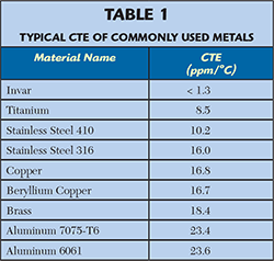
The first approach achieves low temperature sensitivity for the electrical characteristics by using materials with high thermal stability (see Table 1).1 A material very suitable for the realization of resonating cavities and filters for space applications is aluminum; due to its relatively low density, good thermal conductivity, good machinability and low cost. Unfortunately, aluminum has a rather high thermal expansion coefficient (CTE) of 23 ppm/°C. Conversely, a material like invar is nearly ideal from the standpoint of mechanical stability, with a CTE of about 1.6 ppm/°C (or lower, depending on the alloy). But invar, which is an iron-nickel alloy (i.e., some sort of stainless steel), has a number of drawbacks: a high density (8050 kg/m3 as compared to aluminum’s 2700 kg/m3), poor machinability, low thermal conductivity (more than one order of magnitude lower than aluminum) and poor electrical conductivity (in order to achieve a high Q value, it is essential to silver plate an invar cavity).
The mass penalty for using invar versus aluminum should not be underestimated, especially in satellite applications. Given the density ratio of the two materials (close to 3), a 30 kg invar multiplexer would weight 10 kg if made from aluminum. Assuming launch costs of 15 k€/kg for GTO missions (Arianne V), deploying the aluminum multiplexer would result in launch cost savings of about €300,000. Notwithstanding all of its drawbacks, invar remains the often-selected solution in the realization of thermally stable filters in satellite payloads.
Figure 1 Dielectric-loaded dual-mode filter.
Active and passive temperature control techniques for reducing the temperature range experienced by the microwave component are obviously well suited for ground applications but are much less suitable for on-board use. Fancy solutions based on heat-pipes2 or even high temperature superconductor (HTS) materials have been proposed but are rarely implemented in practice.
Promising alternatives to the use of invar in space rely on different techniques, all aiming at achieving an overall high thermal stability at the component level, while using materials with low thermal stability that are suited for space applications. The most widely adopted approaches are based on the use of bimetal or trimetal temperature-sensitive materials or on shape memory alloys (SMA). In general, a temperature compensation technique for microwave resonators and filters is often based on some degree of ingenuity associated with a good knowledge of the electromagnetic modeling of resonators and of the physical properties of materials.
MICROWAVE DIELECTRIC RESONATORS AND PRINTED CIRCUIT FILTERS
Dielectric Resonators
Dielectric resonators based on microwave ceramic materials are often used in frequency stabilized oscillators (DRO) or as resonators in microwave filters and antennas. Their adoption has been greatly favoured after the development of new dielectric compositions, achieving high permittivity, high quality factor, low temperature coefficient of permittivity and low fabrication cost. Dielectric resonators are also used to load the cavities of dual-mode filters, thus shrinking their dimensions (see Figure 1).3,4
The temperature coefficient of the resonant frequency of a dielectric resonator, τf, is given by:
where f0 is the resonant frequency and Δf is the total frequency variation corresponding to a temperature shift ΔT. The temperature coefficient τf is a function of three other temperature coefficients: τe, the temperature coefficient of the dielectric constant, τc, the temperature coefficient of the cavity surrounding the dielectric resonator and αL, the temperature coefficient of thermal expansion of the dielectric material. With a proper design, very low values of τf can be achieved.
Microwave Printed Circuit Filters
The same materials used for microwave dielectric resonators are often used to realize microwave printed-circuit thin film filters. High dielectric constant ceramic substrates enable a substantial size reduction (particularly useful at lower microwave frequencies, e.g., L and S-Bands), while also achieving excellent temperature stability (a few ppm/°C) over wide temperature ranges (typically -55° to +125°C).
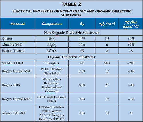
Regarding substrates for microwave applications, a general distinction is made between non-organic (hard) materials, such as quartz, alumina or barium titanate, and organic (soft) materials, such as FR-4, quartz polyimide and all the PTFE-based materials (e.g., Duroid).5 Table 2 summarizes the properties of some commonly used materials.
Soft substrates, with εr in the range of 2 to 10, exhibit different thermal behaviours depending on their compositions. Traditional woven and non-woven “fiberglass reinforced PTFE” materials (εr = 2 - 2.5) have typical thermal coefficients of εr of about -150 ppm/°C (but in some cases they can be as much as -350 ppm/°C). More recent microwave substrates, i.e., glass, PTFE and micro-dispersed ceramic, can achieve much better performance, with thermal coefficients of εr as low as -10 ppm/°C.
MICROWAVE CAVITY RESONATORS AND FILTERS
Cavity resonators are, in general, subject to resonant frequency shifts with temperature, due to corresponding changes in cavity dimensions. Various schemes have been proposed to compensate for this shift. The most obvious would seem that of manufacturing the resonators out of invar or similar materials that have low temperature expansion coefficients; however, invar is expensive, very dense, difficult to process and prone to generating passive intermodulation products (PIM).
An alternative is to partially fill the cavity with dielectric material having a temperature coefficient of permittivity that compensates for the resonant frequency variation. Yet another approach is to construct the cavity from materials having different temperature expansion coefficients. This is done for coaxial re-entrant cavity resonators, but at frequencies above 10 GHz they exhibit relatively poor quality factors. Tuning screws with thermal expansion coefficients different from that of the cavity metal have also been proposed.6,7 A “brute force” approach might be to design the cavity of the resonator in such a way that geometric changes normally resulting from a temperature change are locally restricted or “de facto” suppressed. These types of resonators are referred to as “clamped cavity” resonators.
Figure 2 Temperature compensated cavity filter.
Figure 3 Coaxial cavity resonator geometry.
Some temperature compensated cavity filters have end caps made of a material with a more positive thermal expansion than the CTE of the cavity side walls. This causes the end caps to bend into the filter cavity when temperature increases. In this way, the net change in volume of the cavity is reduced and, with proper design, actually compensated. An example of this approach is shown in Figure 2.8
Many schemes envision either a tuning screw (or screws) or a plunger introduced into the cavity when the cavity is undergoing dimensional changes due to thermal expansion. The tuning elements are usually solidly joined to a temperature sensitive actuator (typically bimetal). Some temperature compensated cavity filters have bimetal or trimetal end caps that bend into a cavity of the filter when temperature increases.
A bimetal is a planar component with two (or more) layers of metallic materials with substantially different CTEs. Over temperature, the differential expansion in the planar dimensions causes a large out-of-plane deflection. Bimetals are commercially used in inexpensive thermostats and temperature sensors (e.g., those used in electric boilers).
As an alternative to bimetal compensation techniques, spring-biased SMA actuators have been proposed. SMAs are materials that can revert to a memorized shape when heated above some threshold. The two major types of shape-memory alloys are copper-aluminum-nickel and nickel-titanium (NiTi). One potential drawback of these materials is their hysteresis, causing actuation to occur at a higher temperature than relaxation.9
Temperature Compensation of a Coaxial Cavity Resonator
Coaxial cavity resonators are the main elements of combline filters (see Figure 3). With an appropriate selection of materials for the housing and the rod, perfect temperature compensation of the resonant frequency can be achieved. The resonating frequency of a coaxial cavity resonator is given by:
where ω0 = resonant frequency at temperature T0
C = capacitance of the gap L1
Z0 = characteristic impedance of the coaxial line
ν = electrical length of the inner conductor
If L1 is small, then:
At temperature T, the capacitance gap becomes:
where a1 and a2 are the CTEs of the walls and inner conductor, respectively. It can be shown that:
where: 
In order to have perfect compensation of the resonant frequency over temperature, the following condition must be verified:
An example of this compensation technique is reported by Yao and Atia,10 where a temperature compensated 8-pole combline elliptic function filter was designed and tested. An equivalent temperature coefficient of -2.8 ppm/°C was achieved.
Figure 4 Temperature compensated TE011 cavity resonator.
Built-In Temperature Compensation of a Ku-Band Output Filter
One example of a temperature compensation technique is shown in Figure 4, where a cavity resonator, based on a TE011 mode, is tuned by a plunger plate. The plunger itself is rigidly fixed to a disk of temperature dilatable material, so that temperature variations cause an axial movement of the cavity wall and tunes the resonating frequency. This temperature compensated cavity was part of a complete pseudo-elliptic four-pole filter, in extracted pole configuration, meant to be part of an output multiplexer (OMUX) at 12 GHz for a television broadcast satellite payload.11
The use of invar in this application was particularly disadvantageous. Due to the high power handling requirement (450 W CW) and the low thermal conductivity of invar, localized temperature rises (hot-spots) of several tenths of degrees above ambient could be generated in the filter. The design takes advantage of a characteristic feature of the TE011 mode resonant cavity that no current flows between the cavity bottom and top walls and the side walls, thus allowing a non-contacting plunger to form one of the end walls without degrading cavity performance.
Knowing that the relationship between the resonant frequency of the cavity F0 and its length L is:
where: L = cavity length;
D = cavity diameter;
Rm= Bessel root for TE011 mode;
it is possible to calculate the plunger displacement needed to compensate any frequency shift caused by temperature variations.
The temperature sensitive actuator is a disk of thermostatic trimetal material clamped in the cavity structure and connected to a copper disk that acts as cavity top wall. The thermostatic trimetal consists of three layers of metal bonded together across the entire interface, each layer having a different CTE. On heating, the composite metal disk changes its curvature, following a law that is linearly proportional to temperature over a wide temperature range. The resulting displacement in the z axis can be calculated so as to compensate for the cavity frequency drift over temperature.
Figure 5 Temperature compensated filter performance at +24ºC and +84ºC.
Figure 5 shows the measured performance of the compensated filter, at ambient and high temperatures. An overall frequency shift of 2 MHz over a ΔT of 60°C was measured, corresponding to an equivalent CTE of 2.3 ppm/°C. This value is very close to the CTE of invar (1.3 ppm/°C) and an order of magnitude smaller than that ofaluminum(23 ppm/°C).
CONCLUSION
The general topic of thermal stability in microwave structures (mainly resonators and filters) for satellite on-board applications was discussed. Temperature compensation techniques are often products of design ingenuity and creativity associated with an in-depth knowledge of the electromagnetic structures and of the physical properties of materials.
References
- C. Wang, “Temperature Compensations for Microwave Resonators and Filters,” IEEE International Microwave Symposium, June 2005.
- B.F. Keats, “Bimetal Temperature Compensation for Waveguide Microwave Filters,” Ph.D. Thesis at University of Waterloo, Waterloo, Ontario, Canada, 2007.
- C. Kudsia, R. Cameron and W.C. Tang, “Innovations in Microwave Filters and Multiplexing Networks for Communications Satellite Systems,” IEEE Transactions on Microwave Theory and Techniques, Vol. 40, No. 6, June 1992, pp. 113321149.
- S.J. Fiedziuszko, “Miniature Dual-Mode, Dielectric-Loaded Cavity Filter,” US Patent 4489293 A, 1984.
- Alcatel Alenia Space, “Microwave Organic PCBs for Space Applications,” 3rd CTB WG Hybrids Technical Presentation Day, ESTEC, May 2006.
- R.V. Basil, L. Ondrups and J. K. Shimizu, “Thermally Compensated Microwave Resonators,” US Patent 4,057,772, November 1977.
- R. E. Jachowski and L. E. Brown, “Compensating Device for Tuned Cavities,” US Patent 4,423,398, December 1983.
- S.B. Lundquist, “Temperature Compensated Filter,” US Patent 5,867,077, 1999.
- B.F. Keats, R.B. Gorbet and R.R. Mansour, “Design and Testing of SMA Temperature-Compensated Cavity Resonators,” IEEE Transactions on Microwave Theory and Techniques, Vol. 51, No. 12, December 2003, pp. 228422289.
- H.W. Yao and A.E. Atia, “Temperature Characteristics of Combline Resonators and Filters,” IEEE International Microwave Symposium Digest, Vol. 3, May 2001, pp. 147521478.
- R. Cameron, M. Lisi and S. Strijk , “Resonateur à Cavitès avec Dispositive de Compensation Thermique,”Brevet d’invention n. 8607497, 16 May 1986, ESA Patent.

Dr. ing. Marco Lisi is presently GNSS services engineering manager at the European Space Agency in the Directorate of Galileo Program and Navigation Related Activities. In this position he is responsible for the engineering and exploitation of services based on the European navigation infrastructures, Galileo and EGNOS. He was previously responsible for the systems engineering, operations and security activities in the Galileo project. In October 2012, he was appointed Special Advisor of the European Commission on European space policies and he served in this position until October 2014. He has worked for more than 30 years in the aerospace and telecommunications sectors, covering managerial positions in R&D, engineering and programs, both in industry and in institutional organizations after receiving his Doctorate in Engineering “Summa Cum Laude” in 1980.