
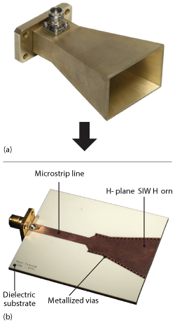
Figure 1 Conventional H-plane horn antenna (a) and its equivalent using SIW technology (b).
A complete Ku-Band direction finding (DF) system using a circular array of eight substrate integrated waveguide (SIW) horns is used to provide full 360° coverage of the azimuthal plane. The antennas are interconnected with commercial monolithic microwave integrated circuits (MMIC) for beam-switching to estimate direction of arrival (DoA). The entire structure is low-profile, lightweight and low cost − suitable for integration in airborne or terrestrial vehicles.
Interest in mmWave components and systems is increasing as new mmWave wireless applications are introduced. To be commercially viable, however, suitable low cost integration technologies are needed for mass production. A very promising technology for high performance, reliability and low cost is substrate integrated waveguide.1 A SIW is an integrated waveguide-like structure fabricated by creating rows of metallized vias in a dielectric substrate that are electrically connected to two parallel metalized surfaces.
Its most significant advantage is the potential to integrate several types of components on the same substrate, including passive components (e.g., filters and couplers), active elements (e.g., oscillators and amplifiers), as well as antennas.1-7 SIW technology also enables high density component integration while having a low-profile and light weight. These features make it attractive for vehicle flush-mounted antenna systems that must minimally affect aerodynamics and aesthetic profiles.
In the case of systems working in the azimuthal plane (e.g., for inter-vehicle communication or DF applications), end-fire radiating elements are needed. Depending on the signal polarization, different types of SIW antennas have been proposed: tapered slots or quasi Yagi–Uda antennas for horizontal polarization,4 and H-plane apertures or horn antennas for vertical polarization.5-7 The latter are of particular interest for applications working near the ground, because horizontally polarized signals are greatly attenuated in these environments. An illustrative example of how to mimic a conventional H-plane horn antenna with SIW technology is shown in Figure 1.
A complete Ku-Band low-profile DF system using SIW horn antennas is motivated by the advantages of this technology. A circular array of eight SIW horns provides full 360° coverage of the azimuthal plane. The antennas are interconnected with commercial MMIC for beam-switching and estimating DoA. The entire structure is low-profile, lightweight and low cost, i.e., suitable to be integrated in airborne or terrestrial vehicles.
SIW Horn Antenna
The SIW horn antenna is a widely used topology for radiating end-fire in system-on-substrates designs.4,5 Its main drawback, however, is the degradation of radiation and matching performance when the substrate thickness, h, is much smaller than the free space wavelength λ0.6 Usually, for h < λ0/6, there is a strong impedance mismatch between the antenna aperture and free space, which results in unwanted back radiation. This is common at frequencies lower than 20 GHz with commercial substrate thicknesses typically lower than 2.5 mm, and why SIW horn antennas are usually not considered for applications in Ku-Band or below.
To overcome this limitation, Esquius-Morote et al.,6,7 introduced a novel SIW horn design incorporating an etched transition after the horn aperture to reduce the mismatch between the aperture and free space (see Figure 2). Excellent impedance matching and radiation performance over a wide frequency range is achieved with the antenna thickness, h, thinner than λ0/10. The authors provide simple design rules and examples. In addition, the horns are tapered following an elliptical shape to obtain a more compact design for a given directivity by combining several TE modes.
Figure 2 Etched transition reduces the mismatch between the aperture and free space.
In this article, these compact and thin SIW horn antennas are used as basic elements in a low-profile beam-switching antenna array for DF applications. Since electronic components are required to implement this functionality, the interconnection between the antennas and commercial MMICs is described.
SIW Horn Antenna-to-MMIC Interconnection
Planar transmission lines, such as microstrip lines (MSL) and coplanar waveguides are commonly used for microwave system integration, and MSLs are the most viable when encapsulated MMICs are used. For this reason, a transition from SIW to MSL is needed.
The system is designed to work at Ku-Band, specifically at a center frequency f0 = 15 GHz. The SIW horn antenna described by Esquius-Morote et al.,7 requires a low permittivity substrate. A good option is 1.91 mm Rogers TMM3 substrate εr = 3.39).8 On the other hand, thin, high permittivity substrates are preferred for MMIC placement since attachment is more convenient and a higher degree of integration is possible. Moreover, if they are encapsulated in QFN packages, usually a 50 Ω input pin of width 0.3 to 0.4 mm is available. Thus, a 0.38 mm Rogers TMM10 εr = 9.56) is chosen on which a 50 Ω MSL has a width MW = 0.34 mm.
Due to the large difference between the thicknesses of both substrates, a vertical transition is used to meet both electromagnetic and mechanical constraints. Several SIW-MSL vertical transitions offering similar performances are proposed, based mainly on probe feeding and slot coupling.9,10 Because the slot coupling transition eases the assembly process and is more robust with respect to tolerances, a slot in the common metal plane between the MSL and SIW is opened for the energy to couple between these two structures (see Figure 3). TW defines the slot width, TL the slot length and MS the microstrip stub length.
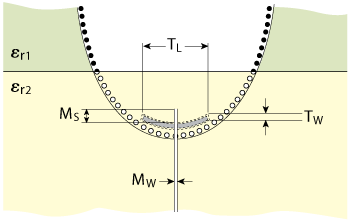
Figure 3 Slot in the common metal plane between the MSL and SIW for coupling between the two structures.
In a slot coupled transition, the forward and backward travelling waves of the electric field excited by the slot are in opposite direction, therefore, the slot must be opened as close as possible to the shortest end of the SIW for a maximum power transfer.10 Despite large differences in permittivity and thickness, this transition offers a good wideband behavior.
Three element SIW Horn Array
A three element SIW horn antenna array is used to test antenna performance when fed by the multilayer transition. Measurements from this prototype are subsequently used in the design of a complete circular array of eight elements. In practice, one element of the complete array exhibits the same behavior as the central one in this threeelement prototype since its performance is mainly affected by the adjacent horns.
Each SIW horn has the same dimensions as the one described by Esquius-Morote et al.,7 and after an optimization process, the SIW-MSL transition dimensions are determined to be TW = 0.6, TL = 8.1 and MS = 1.7 mm. In order to obtain an overlap between adjacent beams of approximately -3 dB, the horns are placed on a circle of 52 mm radius with a 45° separation. The layered view of the prototype is shown in Figure 4. In this case, instead of MMICs, three SMA connectors are placed after the MSLs to measure antenna performance.
Measured S-parameters are plotted in Figure 5. All three horns have reflection coefficients below -10 dB over a 20 percent bandwidth (between 14.2 and 17.5 GHz). Due to the nearly enclosed structure of the SIW horn antenna and good design of the multilayer transition, mutual coupling between horns is practically negligible. In fact, measured values of |S12| are below -40 dB over the entire frequency range.
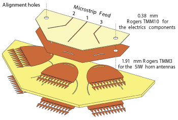
Figure 4 Layered view of three element SIW horn antenna array.
Measured H-plane radiation patterns of the three SIW horns at f0 are superimposed in Figure 6. Despite their low-profiles, the horns provide considerable focusing of the energy frontwards achieving a front-to-back ratio above 15 dB. The -3 dB beam overlap required for beam-switching applications is also apparent. The efficiency of the central horn is 85 percent with a realized gain of 5.6 dBi. Moreover, a cross-polarization level below -20 dB is also measured.
System Design
A beam-switching antenna is an antenna array that can form a set of predefined beams. Once a beam is selected using switches, its received signal is downconverted and processed. Although this type of system is not as flexible as an adaptive array, its main advantage is simplicity and, therefore, low cost. All processing is done in the RF domain so that only one signal must be downconverted: this represents a significant price advantage since the circuits for downconversion are among the most expensive in today’s wireless systems (this is particularly true when working at mmWave frequencies). Moreover, it is important to mention that the performance offered by a beam-switching system is usually sufficient for many common applications.11
A block diagram of the DF electronic system is shown in Figure 7. First, a MicroController Unit (MCU) selects the signal coming from the desired antenna using RF switches. This signal is then split with a directional coupler between the RF output and the control loop. The RF output is the port from where the information carried by the received signal is read. The control loop signal is converted to a proportional DC voltage by means of a Logarithmic Detector (LD) and sent back to the MCU. Finally, after sampling and processing the different antenna signals, the MCU computes the DoA. Amplifiers are also used after the switches and the coupler to compensate for losses.
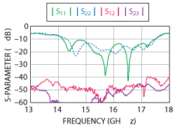
Figure 5 Measured S-parameters of antenna array elements.
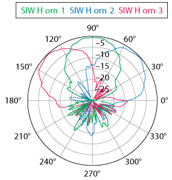
Figure 6 Measured H-plane radiation patterns of the three SIW horns.
All RF electronics are supplied by Hittite Microwave Corp.12 Three HMC641LC4 SP4T switches, two HMC383LC4 amplifiers and one HMC948LP3E logarithmic detector provide good performance within the frequency range. All are QFN GaAs MMICs largely capable of handling typical power levels in a receiving antenna system. It is also important to mention that absorbent material (ECCOSORB GDS-U)13 is needed to suppress amplifier oscillation.
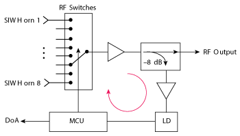
Figure 7 Block diagram of the DF system.
A simple and low-cost peripheral interface controller (PIC), the PIC16F88, is used as the MCU. An internal 10-bit analog-to-digital converter is already included in this PIC which, in this case, is employed to convert the analog output of the logarithmic detector. The control signals for the switches, however, cannot be directly generated by the PIC. As does any common microprocessor, this PIC works with a 5/0 V logic while the SP4T switches work with 0/-5 V logic. A standard multiplexer (MC14053BD) is used to convert the logic level. The PIC is programmed to sample the eight different signals, compare them and compute the DoA. The system functionality is assessed by means of a simple amplitude comparison algorithm based on the measured radiation patterns of Figure 6.
System Evaluation
The complete system is shown in Figure 8. The dimensions and materials used for the SIW horn antennas and the transitions are the same as in the prototype of Figure 4, but the radius of the antenna array is increased to 90 mm in order to accommodate all the required RF and DC components. A shield structure composed of a brass wall and a copper cover is also added to protect the electronics. It is extremely important to protect all the RF components since incoming high frequency signals can easily couple to the transmission/feed lines causing malfunctions, or even damage to sensitive components. For the same reason, the two DC feed lines (+5 and -5 V) are brought inside the shield using feedthrough connectors. Absorbent material (ECCOSORB MCS-U) is also glued onto the interior part of the top cover to dampen any potential cavity resonance.14,15 For demonstration purposes, LED diodes are placed at the brass wall, one in front of each antenna, in order to indicate which antenna is receiving the strongest signal. The output pins of the PIC are used to drive these LEDs (see Figure 8).
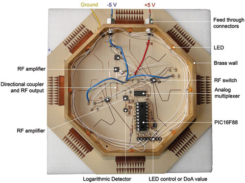
Figure 8 Complete eight element DF system.
Although the MSLs coming from each antenna have the same length (i.e. the same losses), the insertion losses of the SP4T switches are slightly different for each port. To account for this difference, the signal strength received by each antenna under the same conditions is measured at the RF output and the difference compensated later by post-processing in the PIC.
The system was tested in the facilities of the Laboratory of Electromagnetics and Acoustics (LEMA) at the EPFL. The sensitivity of the system is limited mainly by the sensitivity of the logarithmic detector. For a reliable DoA estimation, a signal strength of -65 dBm is required at the antenna. By using the amplitude comparison algorithm, the maximum DoA error is determined to be ±3° between 14.5 and 15.5 GHz. The system consumes around 300 mA (largely due to the amplifiers and the logarithmic detector) and its total weight is 220g (including the shielding structure).
Conclusion
A fully operational direction finding system based on SIW horn antennas has been developed and experimentally verified. Due to the use of SIW technology, the antenna array and thus the whole system is low-profile, lightweight and low cost when compared to similar solutions at the Ku-Band. A simple way to efficiently interconnect these SIW antennas with commercial MMICs is also presented and tested.
This system demonstrates the suitability of SIW technology for high performance commercial applications; and in particular, for flush-mounted configurations in airborne or terrestrial vehicles. Although demonstrated for a simple receiving direction finding application, the concept may be applied to more ambitious applications requiring high data rate transmission.
Acknowledgment
This work was supported by the Swiss Science and Technology Federal Department of Defense, Civil Protection and Sport (DDPS, ArmaSuisse) under the contract Nr 041-18. The authors would like to extend their appreciation to the Hittite Microwave Corporation for providing MMIC samples.
References
- M. Bozzi, A. Georgiadis and K. Wu, “Review of Substrate Integrated Waveguide Circuits and Antennas,” Microwaves, Antennas and Propagation, IET, Vol. 5, No. 8, June 2011, pp. 909–920.
- Y.J. Cheng, P. Chen, W. Hong, T. Djerafi and K. Wu, “Substrate-Integrated-Waveguide Beamforming Networks and Multibeam Antenna Arrays for Low-Cost Satellite and Mobile Systems,” IEEE Antennas and Propagation Magazine, Vol. 53, No. 6, December 2011, pp. 18–30.
- M. Ettorre, R. Sauleau and L. Le Coq, “Multi-Beam Multi-Layer Leaky-Wave SIW Pillbox Antenna for Millimeter-Wave Applications,” IEEE Transactions on Antennas and Propagation, Vol. 59, No. 4, April 2011, pp. 1093–1100.
- Y. J. Cheng and Y. Fan, “Millimeter-Wave Miniaturized Substrate Integrated Multibeam Antenna,” IEEE Transactions on Antennas and Propagation, Vol. 59, No. 12, December 2011, pp. 4840–4844.
- R. Suga, H. Nakano, Y. Hirachi, J. Hirokawa and M. Ando, “Cost-Effective 60-GHz Antenna Package With End-Fire Radiation for Wireless File-Transfer System,” IEEE Transactions on Microwave Theory and Techniques, Vol. 58, No. 12, December 2010, pp. 3989–3995.
- M. Esquius-Morote, B. Fuchs, J. Zürcher and J. R. Mosig, “A Printed Transition for Matching Improvement of SIW Horn Antennas,” IEEE Transactions on Antennas and Propagation, Vol. 61, No. 4, April 2013, pp. 1923–1930.
- M. Esquius-Morote, B. Fuchs, J. Zürcher and J. R. Mosig, “Novel Thin and Compact H-Plane SIW Horn Antenna,” IEEE Transactions on Antennas and Propagation, Vol. 61, No. 6, June 2013, pp. 2911–2920.
- Rogers Corp., TMM® Laminates, www.rogerscorp.com/acm/producttypes/8/TMM-Laminates.aspx, accessed July 2014.
- A. Suntives and R. Abhari, “Transition Structures for 3-D Integration of Substrate Integrated Waveguide Interconnects,” IEEE Microwave and Wireless Components Letters, October 2007, Vol. 17, No. 10, pp. 697–699.
- T.Y. Huang, T.M. Shen and R.B. Wu, “Design and Modeling of Microstrip Line to Substrate Integrated Waveguide Transitions,” Passive Microwave Components and Antennas - InTech, Ch. 11, April 2010, www.intechopen.com/books/passive-microwave-components-and-antennas, accessed July, 2014.
- A.F. Molisch, “Wireless Communications, Second Edition,” John Wiley & Sons Ltd., 2010, Ch. 20.
- Hittite Microwave Corp., www.hittite.com, accessed July 2014.
- Emerson & Cuming Microwave Products, www.eccosorb.com, accessed July 2014.
- P. Dixon, “Theory and Application of RF/Microwave Absorbers,” Emerson & Cuming Microwave Products Tech Notes, 2012.
- P. Dixon, “Cavity-Resonance Dampening,” IEEE Microwave Magazine, Vol. 6, No. 2, June 2005, pp. 74, 84.