
Filters are used in communications systems to keep unwanted signals from propagating through a network. These signals may be interferers from other systems, or they may be generated by the nonlinear behavior of components within the network.
Side-coupled filters constructed from microstrip on printed circuit boards (PCB) are widely used throughout the industry because of their low cost and manufacturability. A side-coupled filter, also known as a parallel edge-coupled filter,1 is built by combining several sections of coupled transmission lines, in which each section is offset from the previous section. In addition to a relatively large footprint, one of the drawbacks of the side-coupled filter is limited rejection of the second harmonic. This application note demonstrates a design approach that reduces this problem: adding notch filters improves the rejection without significantly affecting the filter’s passband performance.
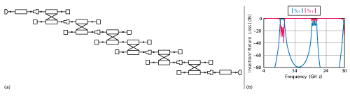
Figure 1 The schematic topology of the initial filter design (a) and modeled |S21| and |S11| responses (b).
From user-defined filter characteristics, such as the passband frequencies, passband ripple and rejection at the stopband, an initial filter design was created using the filter synthesis tool in NI AWR Design EnvironmentTM Microwave Office. The resulting circuit (see Figure 1a) defines the microstrip layout for manufacturing and electromagnetic (EM) analysis. The filter’s simulated performance is shown in Figure 1b.
To reduce susceptibility to EM interference, the filter can be housed in a closed channel or waveguide. There is a risk, however, of higher-order waveguide modes unless the waveguide’s cutoff frequency is higher than the highest rejection frequency. In this design example, transmission lines are added between the pairs of coupled lines, allowing the pairs to be rearranged so they are in-line.2

Figure 2 The schematic topology of a tapped in-line side-coupled filter.
This change results in a narrower footprint, enabling a waveguide with a higher cutoff frequency to be used to house the filter. Figure 2 shows a topology of a tapped in-line side-coupled filter3 with the added microstrip lines between all pairs.
Adding Notch Elements
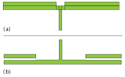
Figure 3 A second harmonic notch filter inserted between the coupling sections (a) and with the notch filter flipped upward to reduce the area of the filter (b).
To improve second harmonic rejection, open circuit microstrip stubs are added to the filter. They are sized to be a quarter wavelength long at the secondharmonic of the passband center frequency. At the second harmonic, the stub’s open circuit impedance will be transformed to a short circuit on the transmission line that connects the coupled pairs. This short suppresses the second harmonic of the passband. The capacitive loading of the open stub in the passband will only slightly impact the performance.
Figure 3a shows how the open stub is inserted in the side-coupled filter, by adding interconnecting transmission lines between the coupled-line pairs. The design can be made more compact, especially for higher frequencies, by flipping the stub upwards (see Figure 3b). The stubs make the filter wider, even if flipped; using radial stubs and bending them will help minimize the footprint. Optimizing the circuit model, then analyzing the EM performance, led to the layout shown in Figure 4.

Figure 4 Radial stubs are used to reduce the size of the bandpass filter with notch filtering.
The filter dimensions enable it to be housed in a WR22 waveguide, which has a cutoff frequency of 26.3 GHz. The simulated insertion loss and return loss of the filter are plotted in Figure 5, comparing the performance in waveguide to open microstrip. While there is a slight upward frequency shift of the filter in waveguide, the second harmonic rejection is as good as before. Since the waveguide changes the filter response, a fine-tune redesign is necessary.

Figure 5 Simulated responses of the open microstrip filter (blue and green) and inside a WR22 waveguide (red and purple).
The coax to connector model can be included in the design using the AnalystTM 3D finite element method (FEM) EM simulator. Separately, the coax-to-microstrip transition can also be modeled and, if necessary, a matching section can be added. Looking at the connector transition alone (see Figure 6), there is no significant mismatch up to the second harmonic, and the insertion loss of 2 × 0.11 dB = 0.22 dB in the passband is as expected.
The geometry and mesh shown in Figure 7 was used for the complete simulation, resulting in the filter response shown in Figure 8. Insertion loss has increased 0.15 dB, and the second harmonic rejection is better than 50 dB. The WR22 waveguide and connectors protect the filter from any outside interference without significantly changing the filter response.
For comparison, the same filter was simulated in a WR42 waveguide, which has a 14.1 GHz cutoff; the results are also shown in Figure 8. The second harmonic rejection is 30 dB less, since WR42 is big enough to propagate at the second harmonic, leading to considerably poorer rejection.
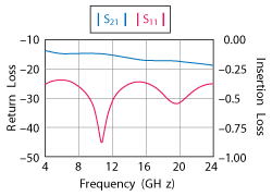
Figure 6 Return loss and insertion loss of the coax-to-microstrip transition.

Figure 7 Composite model of the filter in the WR22 waveguide, including the coax connectors.
Conclusion
The use of an in-line topology for a side-coupled microstrip filter results in a narrower footprint with minimal impact on filter performance. Incorporating notch filters for second harmonic rejection is practical and achieves 50 to 60 dB rejection with minimal degradation in the passband performance. For a filter mounted in waveguide or a closed channel, the side-coupled topology improves the rejection of higher frequencies up to the waveguide cutoff.
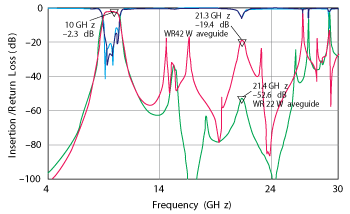
Figure 8 Simulated responses of the filter integrated in WR22 (solid line) and WR42 (dashed line) waveguides, including the coax connectors.
References
- G. Matthaei, L. Young, E.M.T. Jones, “Microwave Filters, Impedance-Matching Networks and Coupling Structures,” Artech House, Norwood, Mass., 1980.
- C. Chang and T. Itoh, “A Modified Parallel-Coupled Filter Structure That Improves the Upper Stopband Rejection and Response Symmetry,” IEEE Transactions MTT-39, February 1991.
- J.S. Wong, “Microstrip Tapped-Line Filter Design,” IEEE Transactions MTT-27, January 1979, pp. 44–50.
Victor Sharir is a senior life member of IEEE. He started Galormic in 1991, where he focuses on design, development and manufacturing of microwave and millimeter wave filters and multiplexers. His designs are used by several Israeli companies, including Rafael, Elta, Elisra and Panasonic Aereo. He was previously a research engineer at Rafael (1972-1991), where he developed design software and hardware for filters and multiplexers using various technologies: waveguide, stripline, microstrip and coaxial. Sharir was introduced to microwave engineering by Dr. Leo Young at Technion in Haifa in 1971.
Benny Haddad is the NI AWR Group technical manager for Israel, where he provides product support for the Israeli market. His experience includes high frequency hardware and software tools, and RF circuit and systems design. Prior to joining NI AWR, he was a senior application engineer at RDT. He served as an RF R&D engineer for Mini-Circuits and Alvarion. Haddad received his B.Sc. degree from the Technion, Israel.
Jaakko Juntunen obtained his M.Sc. in mathematics and applied physics at Helsinki University of Technology and continued graduate studies in the field of radio engineering and computational electromagnetics. He completed his doctoral degree in 2001, with a thesis focusing on the finite-difference time-domain (FDTD) method. After graduation, he worked as the customer service manager at APLAC Solutions Corp., as a regional sales manager at AWR-APLAC Corp. and as an electromagnetic application specialist at NI AWR. Juntunen is currently a sales director at Optenni Ltd., a software company developing professional antenna matching optimization solutions.