
A tapered chamber is traditionally constructed using a square based pyramidal shaped taper that transitions to an octagon and then finally into a cylindrical launch section. This approach is related to the manufacturability of different absorber cuts. In this article, we introduce a chamber where the conical shape of the launch continues throughout the entire length of the tapered chamber. The results of free space VSWR measurements at different frequencies over a 1.5 m diameter quiet zone (QZ) are presented. The conical taper appears to have a better illumination wave front than the traditional approach and better QZ VSWR levels even at frequencies above 2 GHz.
As with all antenna chambers, when the frequency increases, the usable or far field illuminated QZ is reduced. At a 12 m distance from the feed to the turntable, the quiet zone at 8 GHz is reduced to 45 cm. A solution to extend the quiet zone at high frequencies employs a large dielectric lens installed in front of the turntable to improve the phase distribution of the field. A lightweight, broadband lens with a diameter of 2 m was developed and weighs just 35 kg with a focal length of 10 m. With the lens installed, the usable far field QZ is increased, allowing electrically larger antennas to be measured in the chamber. The use of the lens can also be applied to traditional square cross-section tapered chambers.
Background
Tapered anechoic chambers have been around for almost 50 years,1,2 introduced to address issues present in rectangular chambers at frequencies below 500 MHz.3,4 At lower frequencies, high gain antennas used in an antenna measurement range become physically large and can be difficult to handle inside an anechoic chamber, so less directive antennas are used. These radiate more energy to the side walls, ceiling and floor of the chamber forcing it to grow in size in order to accommodate thicker absorbers needed to reduce reflections. Tapered anechoic chambers were introduced to solve this low frequency problem. Instead of trying to eliminate specular reflections in the quiet zone, the specular area is brought closer to the measuring antenna and the specular reflections are used to create a QZ illumination.2,5 Traditionally, tapered anechoic chambers were built having a square based pyramid as the taper (see Figures 1 and 2). To better accommodate different feed antennas, the square section may be gradually transformed to a cylindrical cross section taper. These changes in cross section require a lot of special cuts of absorber to make the transition from the conical section to the square section as smooth as possible and to create the illumination in the QZ.2-5

Figure 1 A typical tapered anechoic chamber.
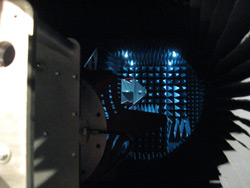
Figure 2 Shaping from square to octagonal cross-section at the feed.
The design presented in this article introduces a conical taper (see Figure 3). The entire tapered structure maintains a constant angle and a circular cross section. The tapered section is about 10 m in total length. Results for the free-space VSWR6 are presented and compared with similar chambers employing a traditional design. To improve performance at high frequencies a dielectric lens is used to create a plane wave behavior.7
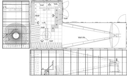
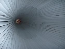
Figure 3 The conical tapered anechoic range plan and elevation (a), and a picture of the taper section (b).
Measured Results
The chamber QZ is scanned using free space VSWR tests6 at a series of frequencies from 200 MHz to 18 GHz. The chamber is lined with 60" (152 cm) curvilinear absorbers on the back (i.e., receive) wall and a combination of 24" (61 cm) pyramidal absorbers and 36" (91.44 cm) on the sidewalls, floor and ceiling. The tapered section has a specially cut wedge material that lines the tapered section from the feed location to the QZ area. The wedges range from 18" (45.72 cm) at the QZ end to 8" (20.32 cm). Figure 4 shows a picture of the conical treatment. The tapered section is built inside an RF shielded room to avoid outside interference during measurements.
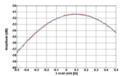
Figure 4 The tapered section as seen from the feed location.
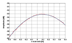
Figure 5 The scanning antenna at the QZ viewed from a point right behind the source antenna at the apex of the taper.
The source antenna is an ETS-Lindgren model 3164-06 dual linearly polarized open boundary quad-ridge horn,8 rated from 300 MHz to 6 GHz. In this application, the antenna is used from 200 MHz with attenuators at the feed to reduce the effects of the high VSWR. The QZ is scanned with an ETS-Lindgren model 3106B dual ridge horn. The scanning antenna and source antenna are shown in Figure 5.


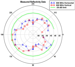
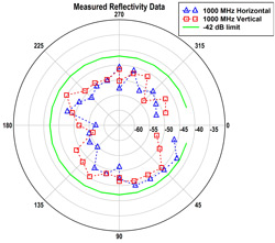
Figure 6 Reflectivity results for the conical tapered chamber at 200MHz (a), 400MHz (b), 800 MHz (c) and 1 GHz (d).
Figure 6 shows reflectivity levels of the QZ versus direction for horizontal and vertical polarizations. Results are shown for 200, 400, 800 and 1,000 MHz. All of these results are measured with the source antenna at a fixed position in the apex of the taper. The antenna is commonly moved as frequency changes to maintain the phase center close to the reflections and maintain a QZ illumination free of ripples.3,4
For frequencies above 2 GHz, an ETS-Lindgren 3164-05 dual linearly polarized open boundary quad-ridge horn, rated from 2 to 18 GHz, is used. For scanning the QZ, a series of standard gain horns are used with gains ranging from 10 to 20 dBi. Additionally, since a smaller horn is used as the source, it is positioned inside an extension of the conical taper. Figure 4 shows one of the two halves that make up this high frequency extension.

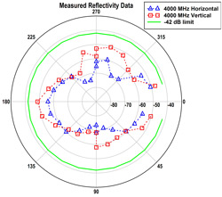
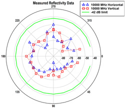
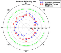
Figure 7 Reflectivity levels in the QZ versus angle at 2GHz (a), 4GHz (b), 10GHz (c), and 18GHz (d).
Figure 7 shows the results of the scans at high frequencies. As discussed by Rodriguez and Hansen,5 tapered chambers are better suited for low frequencies and care must be taken to properly position the source antenna. However, it is possible to use them at these high frequencies once the chamber is characterized.
Comparison with Traditional Chambers
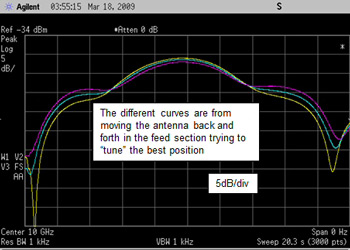
Figure 8 Data for a transverse scan of a traditional chamber using the same horn used in the conical design.
Comparison with traditional chambers is difficult. There are no two identical chambers that have the exact same absorber treatment with the exception of the taper geometry. A qualitative comparison, however, suggests some advantages. With traditional chambers, antennas with gains of 16 dBi and above are required to achieve adequate illumination in the QZ. It appears that one of the features of the conical taper is that lower gain antennas can be used. At 10 GHz, the source antenna has a directivity of 12 dBi,8 whereas the conical quad ridge horn used in many traditional tapered anechoic chambers has a directivity of 14 dBi. The open boundary ridge horn is successfully used in the conical chamber design; however, when used in a traditional chamber, a smooth amplitude taper is not achieved (see Figure 8).
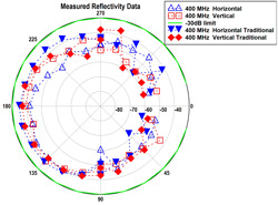
Figure 9 Comparison with a traditional chamber.
In Figure 9, a comparison of the reflectivity of the conical tapered chamber and a traditionally implemented chamber at 400 MHz shows a slight difference in back wall reflectivity (180°), but this is related to differences in absorber treatment between the chambers. For the traditional chamber, one can see a large variation in reflectivity for the horizontal polarization as the direction changes from 15° to 60° on either side of the source antenna. These variations are not seen in the conical tapered chamber.
The chamber is configured with two ranges, a far field tapered range and a NF-FF planar and spherical range. Figure 3 shows the plan of the chamber with the two ranges. The antenna under test uses the same positioner for both ranges, and the QZ is the same as well. For the spherical range the probe is located between the QZ and the planar scanner on the opposite wall. The planar scanner can be used for testing high gain arrays. These arrays can be positioned at the QZ or closer to the scanner by mounting them on a tripod, depending on the frequency of operation or the size of the scanner.
Increasing the QZ Size Using an RF Lens
While the tapered chamber is used to overcome some of the limitations of the standard rectangular chamber for antenna testing at lower frequencies, the size of its quiet zone decreases significantly as frequency increases. For example, the tapered chamber installed at the National University of Singapore (NUS) has a quiet zone of 1.4 m at 500 MHz but only 45 cm at 8 GHz. To increase the quiet zone at the higher frequencies, a custom RF lens is integrated inside the chamber. We are not aware of any other method to increase the quiet zone without physical alterations to the original chamber.
The design of the RF lens is based on the principle of optical refraction to transform a spherical wave from a point source to a planar wave. By precisely controlling the dielectric constant of the lens, the focal length of the lens can be customized based on the lens aperture.
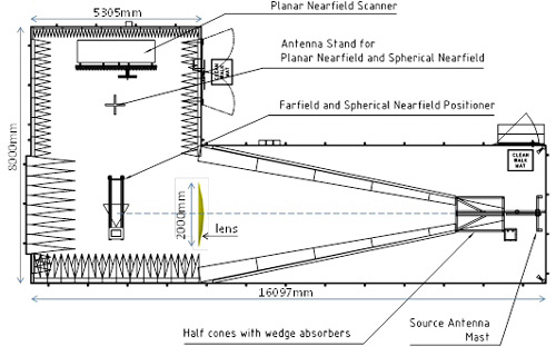
Figure 10 Placement of lens in tapered chamber.
A plano-convex RF lens is integrated into the tapered chamber at NUS (see Figure 10). Its focal length (f) of 10 m is equal to the distance between the source antenna and the end of the chamber’s tapered section. The diameter of the lens is chosen to be 2 m in order to cover a large area of the chamber’s aperture, while allowing easy mobility of the lens inside the chamber.
The lens has a comparatively high ratio of the size of the planar wave front to the lens diameter (a factor of about 0.7D, where D is the diameter of the lens). Hence, a 2 m diameter lens can produce a 1.4 m plane wave front. The profile P(x,y) of the lens is designed using the following equations from Kraus and Marhefka:9
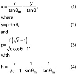
The variables are defined in Figure 11.
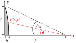
Figure 11 Lens geometry.
Given its size (2 m), the RF lens cannot be manufactured with traditional dielectric materials due to the difficulty of controlling permittivity throughout the lens to a high degree of accuracy. Furthermore, it would be extremely heavy (~1,000 kg), making installation difficult and requiring a special support structure, potentially causing undesirable diffractions.
To overcome these issues, a new low-loss, lightweight metamaterial manufactured by Matsing Pte Ltd. is used. The material allows the control of the dielectric permittivity to a high degree of accuracy. It has extremely low-loss (ε" < 10-4). Its low density (40 kg/m3) means that the 2 m lens weighs only 35 kg, making it portable and easily installed. The material is also isotropic and broadband, making the lens suitable for both vertical and horizontal polarizations over a wide range of frequencies.
Numerical Analysis
The performance of the lens is first evaluated using FEKO EM simulation software. A half-wavelength dipole is placed at the focal length of the 2 m lens. The focal length corresponds to the distance (10 m) between the feed and aperture of the tapered chamber. The field is observed at a vertical plane at 2 m (corresponding to the quiet zone region) on the other side of the lens. For simplicity, the lens and the dipole are simulated in free-space without the tapered chamber since the primary aim of the simulation is to ensure that for the given length of the taper, the lens provides the best possible illumination. Including the chamber with its absorbers in the simulation model would drastically increase the problem size and complexity beyond the capability of the numerical package at these high frequencies.
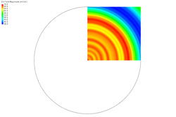
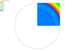
Figure 12 Predicted field distribution at 8 GHz, both in magnitude (a) and phase (b).
Figure 12 shows the predicted fields (for a quadrant) at 8 GHz. The circles in the plots represent the outline of the 2 m lens. Cuts of the fields along the lens diameter are shown in Figures 13 and 14 for 2 and 8 GHz, respectively. The fields of the dipole in the absence of the lens are superimposed in the figures for reference. For ease of comparison, the magnitudes are normalized to their respective mean values -- the phase without the lens is normalized to its peak value and the phase with the lens is normalized to its mean value. From these figures, it is observed that the field with the lens deviates slightly from the dipole field due mainly to diffraction from the lens. However, the lens significantly reduces the large phase variation of the dipole field, producing a reasonably good plane wave in the vicinity of the quiet zone of the tapered chamber.
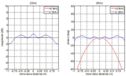
Figure 13 Computed field distribution at 2 GHz.
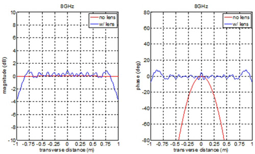
Figure 14 Computed field distribution at 8 GHz.
Measured Performance
The lens is installed at the aperture of the tapered chamber as shown in Figure 15 using a special frame made from low reflection material to easily place and hold it. For the field measurement of the quiet zone, a simple linear scanner is set up as shown in Figure 16. A broadband dual-ridged horn is used as the probe antenna. The field is measured along an axis transverse to the lens axis at about 2 m separation. The lens is then removed and the measurement repeated.
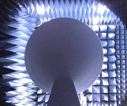
Figure 15 View of the lens from the source antenna.
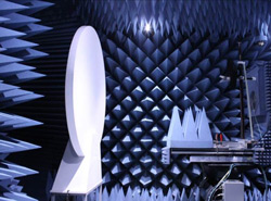
Figure 16 The QZ scanned with the lens in place at the end of the taper section.
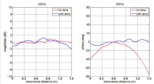
Figure 17 Measured field distribution at 2 GHz.
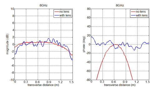
Figure 18 Measured field distribution at 8 GHz.
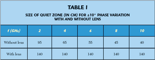
The results at 2 and 8 GHz are shown in Figures 17 and 18, respectively. The magnitudes and phases are “normalized” in the same manner as the numerical results. Note that the transverse distance in these figures, unlike that of Figures 13 and 14 is relative to the start of the measurement position at 0 m. The plots show that the lens has indeed improved the phase significantly without adversely affecting the amplitude. The size of the quiet zone for ±10° phase variation with and without the lens is summarized in Table 1, demonstrating that the lens has significantly improved the phase performance of the tapered chamber. Measurements are also done from 500 MHz to 1 GHz to confirm that the lens does not affect the original quiet zone of the chamber at low frequency.
Conclusion
This article introduces a new approach to manufacturing tapered anechoic chambers that provides good QZ reflectivity results over wide frequency ranges. Additionally, it appears to allow the use of lower directivity antennas than the ones used in traditional chambers. A lower directivity antenna provides a smaller amplitude tapers across the QZ, reducing errors during gain measurements. With the addition of an RF lens, the phase of the chamber’s quiet zone at higher frequencies (2 to 10 GHz) is significantly improved. The lens provides a quick and easy way to enhance the performance of the tapered chamber. Its light-weight construction enables easy user installation. The NUS tapered chamber with an RF lens is now capable of far field measurement of relatively large antennas from 0.3 MHz to 10 GHz.
References
- W.H. Emerson and H.B. Sefton “An Improved Design for Indoor Ranges,” Proceedings of the IEEE, Vol. 53, No. 8, August 1965, pp. 1079-1081.
- H. King, F. Shimabukuro and J. Wong, “Characteristics of a Tapered Anechoic Chamber,” IEEE Transactions on Antennas and Propagation, Vol. 15, No. 3, May 1967, pp. 488-490.
- Electromagnetic Anechoic Chambers: A Fundamental Design and Specification Guide, Wiley-Interscience, John Wiley and Sons and IEEE Press, Piscataway, N.J., 2002.
- V. Rodriguez, “Using Tapered Chambers to Test Antennas,” Evaluation Engineering, Vol. 43, No. 5, May 2004, pp. 62-68.
- V. Rodriguez and J. Hansen, “Evaluate Antenna Measurement Methods,” Microwaves and RF, October 2010, pp. 61-67.
- R.E. Hiatt, E.F. Knott and T.B.A. Senior, “A Study of VHF Absorbers and Anechoic Rooms,” Technical Report 5391-1-F, University of Michigan, February 1963.
- V. Rodriguez, S. Matitsine, T.T. Chia, P. Lagoiski, L. Matytsine, M. Matytsine and P.K. Tan, “A Cone Shaped Tapered Chamber for Antenna Measurements Both in Near Field and Far Field in the 200 MHz to 18 GHz Frequency Range and Extension of the Quiet Zone using an RF Lens,” Journal of the Applied Computational Electromagnetic Society, Vol 28, No. 12, December 2013, pp. 1162-1170.
- ETS-Lindgren horn, www.ets-lindgren.com/pdf/3164-05.pdf.
- J.D. Kraus, R.J. Marhefka, Antennas for All Applications, 3rd edition, McGraw-Hill, 2001.
Vicente Rodriguez attended Ole Miss, in Oxford Miss., where he received his B.S.E.E in 1994, his M.S. in 1996 and Ph.D. in 1999. Dr. Rodriguez joined ETS-Lindgren as an RF and Electromagnetics engineer in 2000. In 2004 Dr. Rodriguez became senior principal antenna design engineer, placing him in charge of the development of new antennas. In 2006 Dr. Rodriguez became antenna product manager, placing him in charge of development, marketing and maintenance of the antenna product line. Dr. Rodriguez is the author of more than 50 publications and holds patents for hybrid absorber and dual ridge horn antennas.
Serguei Matitsine graduated with honors from the Moscow Institute of Physics and Technology in 1979 and received his Ph.D. in 1982. From 1982-1984 he held the position of senior researcher at the Institute of Radio-Engineering and Electronics of the Russian Academy of Sciences. From 1984 until 1995 he has held several positions including senior researcher, head of the electromagnetic laboratory and deputy director at the Institute of Theoretical and Applied Electromagnetics of Russian Academy of Sciences. In 1995 Dr. Matitsine joined the research and development group at Singapore Technologies Aerospace as technical director and later moved to the position of chief engineer. Since 2001 Dr. Matitsine has also been working at Temasek Laboratories of the National University of Singapore as an adjunct senior principal research scientist. He is also the chairman and technical director of Matsing Pte. Ltd. He has more than 60 publications in these areas, as well as four patents.
Tse-Tong Chia received his B.Eng. degree with first class honors in 1986 from the National University of Singapore, and his M.S. and Ph.D. in 1991 and 1994, respectively, from Ohio State University. He has been with the DSO National Laboratories, in Singapore since 1986, where he is currently a distinguished member of the technical staff. Chia was a laboratory head from 1995 until 2010 when he stepped down to focus on research. He is also currently a principal research scientist in the Temasek Laboratories at the National University of Singapore. His research interests include computational methods for electromagnetic scattering and installed antenna performance, as well as the use of lenses for antenna applications.
Pavel Lagoiski received his B.S. E.E. from the National University of Singapore in 2010. Since then he has held the position of engineer at Matsing Pte. Ltd. His research interests include antenna measurement system and RF lenses.
Leo Matytsine received his B.S. from the University of Southern California in 2009 and his MBA from the Australian Global School of Management in 2013. He has been with Matsing Pte. Ltd. since 2009 and currently holds the position of director. His interests include RF convex lenses and antenna measurement systems.
Michael Matytsine received his B.A. from Chapman University in 2006 and his MBA from La Verne University in 2010. He has been with Matsing Pte. Ltd. since 2006 and currently holds the position of director. His interests include Luneburg and convex RF lenses.
Peng-Khiang Tan received his degree in electronic and computer engineering from Ngee Ann Polytechnic in 1999 and his Bachelor of Technology in Electronics Engineering (second Class Honors) from the National University of Singapore in 2008. He currently works as a laboratory technologist within the antenna group at the Temasek Laboratories of the National University of Singapore.