
The rapid advances in radio frequency (RF) technology after World War II provided the building blocks for the highly agile radar and high speed communications systems in use today. Innovations in RF signal processing, integrated electronics and miniaturization of interconnects have contributed to the evolution of radar from large and cumbersome narrow-bandwidth systems requiring mechanical articulation of the antennae to locate and track targets, to the active electronically scanned array (AESA) radar systems in use today. The AESA radar systems can form multiple beams on a single antenna panel, with the capability to track numerous targets simultaneously, providing a significant advantage to the modern warfighter on land, at sea and in the air.
Communications systems have also evolved to have greater bandwidth and range that enable the secure encrypted transmission of large packets of data. As open-architecture embedded systems grow smaller and more sophisticated, designers are looking for ways to package a larger number of interconnections into high-density arrays. The modularity of embedded systems and the need to integrate RF functionality offered the opportunity to create a separable RF daughtercard/backplane interface within the system architecture.
Origins of VITA 67
Before the arrival of open architecture VPX and the requirement for separable mixed signal connectivity at the backplane/daughtercard interface, there were no standards to ensure interoperability of RF, optical, signal and power. Providers of equipment either used front panel connectors or customized coaxial backplane configurations for analog, video and RF signals. Although many interconnect products were applied for this purpose - multi-sourced, interchangeable connectors were not common.
Systems integrators saw the need for separable, multiconductor, blind-mate RF connections at the daughtercard/backplane interface to simplify the routing of RF signals and eliminate the need for front panel RF cable jumpers. Jumpers present the inherent possibility of cross-connection and/or damaged connectors. A number of VITA 46 committee members recognized the need for a standardized framework for the application of multiple RF blind-mate coaxial interconnects and established a working group within the VITA Standards Organization (VSO). Initially the RF effort was under a subcommittee, VITA 46.14; however, this effort was later broken out into a separate working group. The product of this working group is the “ANSI/VITA 67 Standard for Coaxial Interconnects on VPX.”
Contact Choice and Size Requirements
The requirements of form, footprint and performance for the VITA 67 RF interconnect system were generated from customer input gathered through many voice-of-the-customer (VOC) interviews conducted with major military and aerospace integrators and subsystem suppliers.
With consideration that the RF interconnect structure must fit into existing VPX systems, ANSI/VITA 46 dictated the footprint for the RF modules. The RF modules are required to be a form fit to replace MULTIGIG RT 2 full- and half-size signal connector modules; the contact design must accommodate blind-mate application with total axial float of 2 mm and radial float of 0.25 mm. The connector pitch, which was driven by the requirement to accommodate small diameter (22 to 29 AWG) RF cables with low-transmission-loss characteristics is a compromise between density and performance. The SMPM series connector was chosen for this application because it best satisfies the density, performance, durability and blind-mate requirements. Three main factors favored the SMPM connector:
- Its interface configuration is standardized in MIL-STD-348.
- The connector is 30 percent smaller than the SMP series, yet accommodates the same standard and low-loss 0.047" and 0.086" diameter flexible, conformable and semi-rigid cable sizes.
- Its size permits eight RF contacts to be easily arranged within the footprint of a full-size MULTIGIG RT 2 connector module.
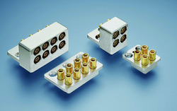
Figure 1 VITA 67 RF modules provide a standardized board-to-board interface. (Source: TE Connectivity)
While SMPM connectors have a maximum operating frequency of 65 GHz, the VITA 67 standard requires only a frequency range of DC to 26.5 GHz. This provides considerable capability to accommodate future requirements. Figure 1 shows VITA 67 modules.
The application of connectors in a blind-mate configuration requires a design that allows sufficient axial and radial float to accommodate the variations in positional tolerances that are common in implementations of blind-mate interconnects. The design must incorporate features that provide accurate placement and critical contact alignment to achieve a proper and reliable connection and avoid damage due to stubbing.
The conventional solution for RF blind-mating is to use a pair of pin contact receptacles with a floating jack-to-jack “bullet” connector between them. This configuration has two separable interfaces per signal path. This approach, however, is problematic because of the dimensional variability where multiple interconnects are used. It is unlikely that all of the connectors will ever be fully mated, due to accumulation of axial tolerance variations. The mating uncertainty of this configuration results in degraded electrical performance caused by a “gap” that introduces an inductive response. This “gap” permits the bullet contact to move when subjected to vibration or mechanical shock and can result in the generation of microphonic noise. This condition is an unacceptable deficiency, considering the level of vibration and mechanical shock performance required by the ANSI/VITA 47 Environmental Specification.
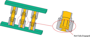
Figure 2 Gap in mated connectors can degrade electrical performance. (Source: TE Connectivity)
The illustration in Figure 2 shows the center connector stack at least material condition (LMC) flanked by two connector stacks at the maximum material condition (MMC), depicting a worst-case scenario where one of the three connector stacks is not fully mated. The jack-to-jack spring bullet is one solution to this tolerance problem; however, it has some signal integrity problems and is costly.
VITA 67 RF modules use a two-connector SMPM configuration: a float-mounted cable jack and a fixed plug receptacle. The interfaces are in accordance with MIL-STD-348, except for a minor modification that increases the plug receptacle entrance diameter from a nominal 0.114" to 0.130" (2.9 to 3.3 mm) to provide a more generous capture range. Furthermore, the outer contact beams on the SMPM jack were analyzed using the ANSYS Workbench platform and configured to optimize contact durability when used in conjunction with a smoothbore receptacle. The SMPM cable jack is spring mounted to allow both axial and radial float. The spring force at preload is set to overcome the mating forces, and the force when fully mated is set high enough to maintain the fully mated condition under shock and vibration.
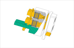
Figure 3 VITA 67 mated pairs. (Source: TE Connectivity)
In the application of float-mounted connectors, the designer should consider that the attached cables contribute to the overall mass of the floating connector and therefore must be supported with an adequate strain relief mechanism. A cross-sectional view of an ANSI/ VITA 67.1 RF module mated pair is shown in Figure 3.
Since the slotted outer conductor on the SMPM jack is a known path for RF leakage, features are required in the RF module design to mitigate cross-channel interference (isolation) and provide immunity from radiated susceptibility and emissions. This is accomplished in the VITA 67 RF module design by positioning the SMPM interface within a metal shell.
When the connectors are fully mated, this configuration benefits from the resulting two overlapping metal rings surrounding the slotted outer conductor of the jack (socket) connector. The overlapping rings improve the isolation between contacts (see Figure 4).
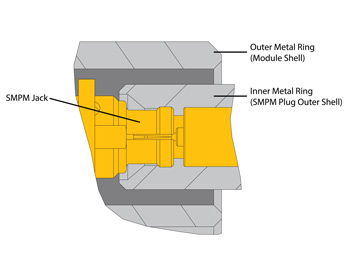
Figure 4 Overlapping metal rings help increase cross-channel isolation. (Source: TE Connectivity)
The VITA 67 contacts are housed in robust stainless steel or aluminum modules that hold four (VITA 67.1) or eight (VITA 67.2) contacts. Contact spacing is 0.240" (6.1 mm), which represents a compromise in combining contact density and electrical isolation. The modules are configured to provide RFI/EMI shielding between the contacts and provide a high level of adjacent channel isolation of at least 100 dB up through 30 GHz. To put this in perspective, under similar conditions, the shielding effectiveness of typical cable assembly is 90 to 100 dB. The physical configuration, electrical performance and durability of the RF module-SMPM interconnect system contributes to the achievement of system performance that meets or exceeds the requirements of the VITA 67 specification.
The two module sizes provide application flexibility. Four-position modules (VITA 67.1) are intended for 3U VPX, in slots P2/J2. Suited for 6U systems, the eight-position modules (VITA 67.2) can be used in slots P5/J5 or P6/J6. Figure 3 shows the modules in a 6U system in slot P6/J6. The modules, of course, are not restricted only to VPX applications. The RF module profile is low enough to support a 0.8" card pitch, and the design has inspired many application specific spin-off configurations with RF contact counts from 1 to 24.
SMPM series RF connectors are available in vertical board-mount and edge-launch versions for application on the backplane and daughtercard. Cabled versions are also available for PCB-mounted applications. Cable designs are available for a wide range of standard cables that includes 0.047" (MIL-DTL-17/151), 0.086" RG-405 (M17/133) semi-rigid cables, conformable cables and flexible cables. There are also a number of high-performance, low-loss and phase-stable cables available for applications requiring these attributes.
Recently, applications have emerged that require low-transmission-loss versions of these small diameter cables. Traditionally, lower transmission loss was achieved by selecting a larger cable size; however, the SMPM series connectors’ small size limits the maximum cable diameter that may be used. The solution is to look to technology for the answer. There are a number of outstanding sources for small-diameter, low-loss coaxial cables. These low-loss cables typically use a larger center conductor and an insulator core of a material and configuration that permits a higher wave propagation velocity than standard cables with a solid insulation core.
Cable-mount backplane and daughtercard connectivity have several benefits over board mounting: the RF performance—i.e., transmission loss and reflection coefficient—achieved when using cables is superior and more predictable than that of in-board transmission line structures. The application of cables typically has a lower installed cost than multilayer RF circuit boards and are easily reconfigured, replaced or repaired. The downside of cable configured interconnects is overall packaging density is somewhat compromised.
Signal Integrity
Once the basic form factors are addressed, the electrical performance of the interfaces must be verified. Overall, this means ensuring signal integrity. Simply put, signal integrity is the preservation of electronic data routed through an electronic system for processing. If unintelligible upon receipt, system function will be impaired. The end user relies on and often takes for granted the effective functionality of electronic systems. The failure of mission-critical electronics in military, aerospace and avionics systems can have dire consequences. With the increasing complexity and density of electronic systems, there are a number of factors that contribute to signal integrity. For an RF interface, the challenge for the signal integrity engineer is to:
- Minimize attenuation and crosstalk
- Minimize degradation of the signal due to reflective, absorptive and resistive losses
- Isolate the signal from interference generated internally from external sources such as power supplies. External sources may be in close proximity or, worse, intentional interference from jammers.
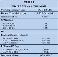
Table 1 summarizes the electrical performance requirements for VITA 67 RF modules.
Testing
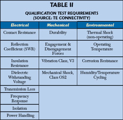
Although the VITA 67 RF modules use SMPM series connectors, much consideration was given to the module design configuration to accommodate the requirements of ANSI/VITA 47-2005 (R2007), “Standard for Design and Construction, Safety, and Quality for Plug-In Units.” A comprehensive test plan, summarized in Table 2, was developed to verify compliance to the specified requirements. A total of 21 VITA 67 RF modules were submitted in eight separate test groups and monitored for compliance to the VITA 67 specification.
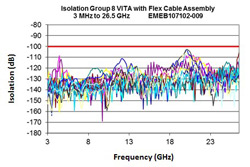
Figure 5 Isolation test results
Swept data was taken for the three frequency bands shown in Figure 5 to verify cross-channel isolation at both the near and far ends. Figure 5 shows the results. In addition, the load on the target channel was removed and the change was noted to be minimal. In all testing, the specification limits were verified.
During vibration and mechanical shock testing, the test specimens were monitored for discontinuities of 10 nanoseconds or greater using an energizing current of 100 mA. No discontinuities were detected.
VITA 67 RF modules were tested for power handling at 105°C, with RF CW power applied at 30 dBm from 3 to 30 MHz and at 20 dBm from 30 MHz to 26.5 GHz. The reflection coefficient (SWR) was monitored continuously and no significant variation was noted.
Integrating VITA 67 into VPX and Applications
VITA 67 multi-position RF modules have been deployed globally in signals intelligence, radar, electronic warfare, and force protection applications. These applications cover the range of environments from naval systems to flight. With some applications using dozens of channels, installation and management of the RF modules and their cables become a new challenge. As with the VITA 66 fiber-optic modules, the interface includes a spring action to maintain engagement and help ensure high performance. This requires the integrators to provide secure injector/ejector and wedge-lock assemblies. Numerous companies have stepped into the VPX chassis space, and a wide variety of hardware catering to these new applications is now on the market.
Another packaging challenge brought about with the introduction of the VITA 67 modules is routing of cables for minimal loss, stability and ease of installation/repair. TE has developed a suite of solutions to assist in harness management, ranging from conformable strain reliefs to lightweight structures with integrated cable management features. These advances have made the integration and deployment of VITA 67 technology very convenient and have hastened the global adoption.
As users gain experience with VITA 67 modules, they are looking toward newer configurations that will offer advanced performance in several areas:
- Higher densities, with pitches under 0.10"
- Higher frequencies 50 to 65 GHz
- Direct board attachment
- More reliable blind-mating (non-stubbing)
As is the trend in electronics and electronic interconnects, evolution is a constant.
Steve Morley is a product development engineer for TE Connectivity, Global Aerospace, Defense & Marine. He has more than 30 years experience designing, testing and analyzing microwave and radio frequency connectors, cable assemblies and components. Connect with Steve at www.designsmarterfaster.com.