
Figure 1 The application space and sub-elements of EW.
Electronic Warfare (EW), in general, involves denying an enemy use of the Electromagnetic Spectrum (EMS) or gathering intelligence of an enemy’s intended actions or capabilities through analysis of electromagnetic (EM) signals they may transmit, either intentionally or unintentionally. Simulation of the spectral environments encountered by an EW system in the field is a complex undertaking and the need for an effective and validated operational test capability cannot be underestimated, while tight budgets introduce a new dimension of complexity. This article discusses the EW environment, the EW test and evaluation process, and off-the-shelf alternatives for simulation requirements.
EW comprises three areas of application: Electronic Attack (EA), Electronic Protection (EP) and Electronic Support (ES) and operates with other types of systems − specifically Intelligence, Surveillance and Reconnaissance (ISR), and radar (see Figure 1). Electronic attack includes jamming of threats using everything from high power barrage techniques to selective deception techniques that offer the advantage of not jamming your own side’s systems as well as your adversaries. Weapon systems are also part of electronic attack in the form of High Speed Anti-radiation missiles (HARM) in addition to actively transmitting decoys. Electronic protection involves managing the spectrum you are using to find clear and safe areas of operation and to ensure your own systems are not overly vulnerable to electronic attack from your adversaries. It also involves control of your own emissions such that your own signals don’t provide a beacon for enemy fire. Electronic support includes systems that are termed Electronic Support Measures (ESM) that provide threat warning, Signal collection and cataloging, and direction finding (DF) where we’ll use the adversary’s emissions to locate them.
Radar can pose a threat in the form of a tracking or fire-control radar or a radar signal from a guided missile. The EW system must identify the threat and take mitigating action. Collectively this is known as electronic countermeasures or ECM. Processing by the radar and the actions to overcome ECM or jamming are known as electronic counter-counter measures or ECCM.
The EW application and specifically ES is closely related and overlaps with the SIGINT or signals intelligence area. The collection, identification and cataloging of various threat signals is a critical part of the EW process and receivers are specifically designed to support this mission. SIGINT is divided into several different sub-areas depending on the type of signals in which we are interested. ELINT and COMINT are the two largest with ELINT or electronic intelligence covering radar signals and
COMINT dealing with communications signals.
ELECTRONIC ORDER OF BATTLE
There are many terms, abbreviations and acronyms associated with EW technology and operations. One that warrants a closer look is the EOB or Electronic Order of Battle. This refers to all the activity in the EM spectrum occurring at any given time in the theater of a conflict. Generating an EOB requires the identification of all emitters in an area of interest using SIGINT techniques to determine their geographic locations or ranges of mobility, characterizing their signals, and wherever possible, determining their roles in the broad organization and configuration of the conflict. The EOB details all known combinations of emitters and platforms in a particular area of responsibility for both sides of the conflict. The simulation and analysis systems that provide this capability are large and expensive. The magnitude of the signal environment they are designed to simulate drives complexity, making them difficult to modify and program. The solution described here is somewhat simpler but also less capable. The assumption is that many of the steps in the test and evaluation process of different types of EW systems do not need to simulate an entire electronic order of battle but various subsets at any one time.
One example of an EW system we want to characterize the performance of is the Radar Warning Receiver (RWR). The primary purpose of the RWR is to issue a warning when a radar signal that might be a threat is detected. The warning can then be used, in conjunction with other systems, to manually or automatically evade the detected threat. Radar warning systems are often capable of classifying the source and type of radar by the signal’s strength, phase and waveform type.
Figure 2 The EW system test and evaluation process.
EW SYSTEM TEST AND EVALUATION
The test and evaluation of an EW system involves several distinct steps (see Figure 2) that progress through different levels of integration with the system by itself and then the system within the host platform such as an aircraft or ship. As we move up this continuum of integration the simulation becomes more complex until a full EOB environment is simulated or operational testing is conducted in the field or on a test range. It starts in the systems integration lab where we ensure the various components and subsystems interoperate together and that system performance meets specification in terms of RF and environmental parameters. The next step is hardware-in-the-loop (HWIL) testing where the full EW system is stimulated with a high fidelity RF scenario providing a simulation of the operational spectral environment to functionally characterize its performance. This is also a good point at which to optimize EW algorithms and evaluate different jamming tactics. After HWIL testing, the system is installed on the operational platform(s) and functionally stressed in a full EOB environment. Finally, testing moves to an open air range to ensure high performance operation in all situations using a variety of tactics. This stage of testing is very costly and the also the least repeatable, so it is critical to push as much of the evaluation activity as possible to the earlier stages of the test process.
The types of test systems and measurements methods used through the process vary beginning with the use of discrete off the shelf instruments in the system integration lab such as spectrum and network analyzers, oscilloscopes and signal generation equipment. Moving into the HWIL stage a higher degree of automation is applied to construct the needed spectral scenarios, synchronize measurements and record results. At the installed system test facility generally large and somewhat customized test systems are used to generate the very complex and dynamic spectral environment required. At the open air range a variety of equipment is employed from off the shelf instruments to customized automated systems.
Figure 3 The basic building blocks of an off-the-shelf EW simulation and analysis solution.
Complex multi-emitter simulators are well suited for EW testing in a complex electromagnetic environment and perhaps an entire EOB; however they can be overkill for simple and iterative system integration and HWIL testing or RWR/ESM threat identification evaluation. Scheduling time on such a system may be difficult as such an expensive asset may be in use up to 24 hours a day. Figure 3 shows the elements required in an EW test system to support a variety of EW receivers and jammer types. These elements can be realized with current off the shelf technology. The core of the simulation side of the system is the arbitrary waveform generator (AWG) enabling playback of any waveform file that can be generated mathematically with software or recorded. Multiple coherent AWG channels may be needed to provide appropriate environment simulation for distributed aperture systems. Upconversion to the frequency range of operation is a critical step in the simulation process as the fidelity of the signals must be maintained.

Figure 4 16 radar emitter waveforms combined and generated from a single AWG channel.
Often the signal scenarios used for EW testing are long and take time to evolve. Waveform memory will be used up quickly when bandwidths are wide and sample rates are high. This means a huge amount of waveform memory beyond what is available internal to the AWG may be required to play the scenario. Different methods of streaming the waveform data may be employed to expand the possible signal scenario length to seconds, minutes or hours. The waveform data could be stored on a deep memory device such as a RAID (redundant array of independent disks) that allows access to a very large memory space. The rate at which data can be streamed is generally limited by the interface between the AWG and the RAID such that the signal bandwidth is well below what is needed for a wideband multi-emitter simulation. Another method is to describe the different pulsed signals contained within a waveform by their temporal parameters such as pulse width and amplitude. This becomes a compressed set of information of what is termed pulse descriptor words (PDW) which are much more manageable, particularly for off-the-shelf tools.
Multiple threat emitters with different characteristics are shown in Figure 4. Here the 16 unique signals have different frequencies, amplitudes, bandwidths and pulse repetition intervals (PRI). The drawback of adding multiple uniquely modulated emitters to a single AWG waveform file is that the dynamic range of the generated signal will be reduced.
Figure 5 shows a measured multi-emitter spectral environment on an oscilloscope using vector signal analysis (VSA) software. The L-Band radar signal is on the far left. Several communication signals including LTE, EDGE, GSM, and WCDMA signals are near the middle of the spectrum, and the S-Band radar signal is on the far right. A second WCDMA signal has been placed within the S-Band radar’s bandwidth. This will allow potential interference effects between the radar signal and the WCDMA signal to be investigated using the VSA software. These various emitters were generated using a single AWG by combining multiple waveform files created using both SW tools and recordings. This was all accomplished using off-the-shelf equipment and software tools.
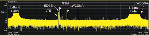
Figure 5 Mixed communications and radar emitters combined into a single waveform file.
Very sophisticated threat signal and scenario simulation can be produced using commercially available off-the-shelf equipment and software tools; however, there are limitations when attempting to create scenarios with a very large number of threat emitters. In this case, a more costly custom system capable of generating perhaps thousands of emitters may be needed; but for many simpler EW simulation needs, a cost effective solution is right there waiting on the shelf.