
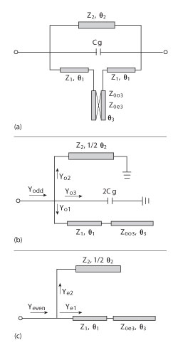
Figure 1 Equivalent circuit of the BSF (a), odd-mode equivalent circuit (b), even-mode equivalent circuit (c).
A compact bandstop filter (BSF), using a coupled stepped impedance hairpin unit and an inner interdigital capacitor, is presented in this article. Detailed theoretical analysis reveals that the filter’s bandwidth and stopband rejection level can be controlled by the upper transmission line’s characteristic impedance, the capacitance or the coupling strength of the coupled line. Based on this theory, a proposed BSF centered at 2.22 GHz with a bandwidth of 81.08 percent has been designed, fabricated and measured. The implementation area is 0.141 λg × 0.158 λg, where λg is the guided wavelength of a 50 Ω transmission line at the center frequency. Good agreement between measured and simulated results is obtained.
Bandstop filters (BSF), important components in the process of sending and receiving signals in telecommunication, play a key role in suppressing noise and spurious signals, which results in a great demand of BSFs with wide stopband and compact size. Conventional BSFs, using series and shunt stubs, exhibit narrow stopband and large size.1,2 Recently, to meet the stringent requirements of wide stopband and compact size BSFs, several methods and structures have been proposed. A wideband BSF, using a tight-coupled hairpin unit, has been presented.3 A dual band BSF, with a dual-mode loop resonator and a cross-coupled capacitor, has been described.4 It achieved a high rejection of the stopband and the 20 dB fractional bandwidth are over 100 and 10 percent, respectively. But because of the parasitic effect of the lumped element, the precise capacitance is hard to control. Another compact BSF, composed of a single quarter-wavelength resonator and anti-coupled lines, was proposed,5 which show the characteristics of wide bandwidth and low insertion loss. The signal interference technique has been used to design wideband BSF with 40 dB fractional bandstop of 22.3 percent.6,7 Parallel coupled transmission line units have been adopted to provide wide stopband characteristics with attenuation poles.8 Meanwhile, the rejection depth and bandwidth of the filters can be controlled by the coupled-line parameters. Two transmission line configurations have been proposed to design sharp-rejection BSF.9 The impedances of the transmission lines can easily control the rejection depth and bandwidth of the BSF.
Owing to the characteristic of simple structure and compact size, the coupled stepped impedance hairpin unit has been used to compose a proposed BSF.10 The fabricated wideband BSF exhibits a measured bandwidth of 75 percent at the center frequency. However, the bandwidth characteristics are far from ideal, especially if the two transmission zeros confine the bandwidth of stopband for only 18 dB.
Here, for the sake of improving the bandwidth characteristics of the BSF, a modified structure, using a coupled stepped impedance hairpin unit and an interdigital capacitor, is presented to realize a higher rejection level. It can be seen that this modified structure can provide another transmission zero due to the introduction of an interdigital capacitor. Thus the additional zero improves the stopband attenuation level and results in a comparatively wider bandwidth, simultaneously.
Filter Analysis
Figure 1 shows the configuration of the proposed filter. The filter is composed of a coupled stepped impedance hairpin unit with an inner capacitor of Cg. As the model is symmetrical, it is useful to simplify the analysis by odd- and even-mode networks.
When the circuit is excited in the odd-mode, the corresponding equivalent circuit shown is obtained. The input admittance of the odd-mode is:
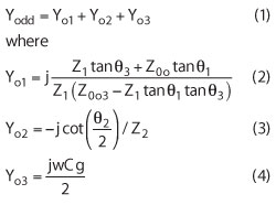
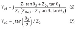
Similarly, when the circuit is excited in the even-mode, the corresponding equivalent circuit is obtained. The input admittance for the even-mode is:

where
The scattering parameters S21 and S11 of the filter are given by
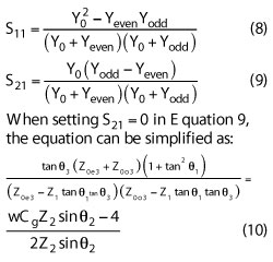
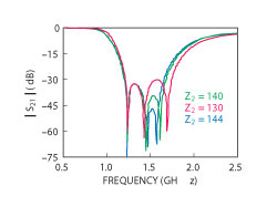
Figure 2 Computed responses of the BSF with different Z2.
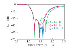
Figure 3 S21 parameter as a function of Cg for fixed Z2.
Based on the theoretical analysis,3 the transmission zeros can be derived from Equation 10. Since the bandwidth of the stopband is mainly dependent on the positions of the transmission zeros which are derived from Equation 10, the bandstop feature can be proved by simulating the same model with diverse parameters.
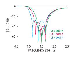
Figure 4 Theoretical transmission responses for different values of M.
As illustrated in Figure 2, the stopband rejection depth can be upgraded by the increase of Z2, when Z1 = 120 Ω, Z0e3 = 50 Ω, Z0o3 = 49 Ω, θ1 = 45°, θ2 = 35°, θ3 = 30°, Cg = 1.1 pF, while two of the transmission zeros move back to the edges of the stopband, leading to a narrower bandwidth and slower attenuation. To observe the effects of the capacitance Cg on the filter response, the theoretical transmission responses of the BSF with different capacitance values are analyzed in Figure 3. In all of the three cases, Z2 = 140 Ω, Z1 = 120 Ω, Z0e3 = 50 Ω, Z0o3 = 49 Ω, θ1 = 45°, θ2 = 35°, θ3 = 30°. Based on the similar analysis above, a lower Cg creates a higher-level stopband rejection. However, an extremely low Cg may lead to the deterioration of the number of the transmission zeros. After taking the actual circumstance and layout into consideration, a moderate Cg is the best choice to balance the rejection performance and the number of the transmission zeros.
From Equations 8 to 10, it can be seen that the transmission lines of the coupled stepped impedance hairpin unit play a key role on deciding the transmission zeros, which are affected by the coupling factor defined by M = (Z0e3-Z0o3)/( Z0e3+Z0o3).
To observe the practical and exact effects of M, Figure 4 shows the S21 of the proposed structure with different coupling factors M, when Z2 = 140 Ω, Z1 = 120 Ω, Cg = 1.1 pF, θ1= 45°, θ2= 35°, θ3= 30°. It has been found that as M increases from 0.002 to 0.019, the rejection level decreases, while the transmission zeros move toward the edges of the bandstop, creating a wider bandwidth and sharper skirts.
Simulated and Measured Results
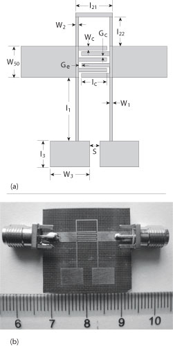
Figure 5 Fabricated wideband BSF (a) layout and (b) photograph.
To verify the above design methodology, a bandstop filter, derived from the prototype, is designed on a 1 mm thick substrate, with a relative dielectric constant of 2.5, for experimental demonstration. After taking the stopband ripple, passband match and the layout into consideration, the impedances of the configuration are set to be: Z1 = Z2 = 156.70 Ω, θ1 = 23.46°, θ2 = 39.54°, Z0o3 = 27.23 Ω, Z0e3 = 29.54 Ω and θ3 = 16.12°. The interdigital structure is employed to realize the required capacitor Cg. The optimized layout and photograph of the fabricated filter are shown in Figure 5. The parameters of the stubs are selected as follows: W1 = 0.2 mm, l1 = 7 mm, W2 = 0.2 mm, l21 = 5.8 mm, l22 = 3 mm, W3 = 6 mm, l3 = 4.42 mm, S = 2.4 mm, Wc = 0.2 mm, Gc = 0.2 mm, Ge = 0.2 mm, W50 = 2.7 mm and lc = 5.2 mm.
The simulated results obtained with Ansoft HFSS and the measured results are displayed in Figure 6, where the two curves show good agreement. From the results, the attenuation rates at the passband transition knees are 71.42 dB/GHz (measured attenuations are 5 and 30 dB at 1.38 and 1.73 GHz, respectively) and 78.13 dB/GHz (measured attenuations are 5 and 30 dB at 2.99 and 2.67 GHz, respectively) on the lower and upper side of the stopband, respectively. The BSF aims to provide three different stopband centers at 1.65, 2.22 and 2.54 GHz. Because of the joint effect and unexpected couplings between the stubs, three transmission zeros located at 1.79, 2.09 and 2.63 GHz appear in the measured S21 response as expected. In addition, with the aid from introducing a transmission zero, the bandwidth of the BSF at 3 dB and 20 dB is increased. The measured lower and upper 3 dB cut-off frequencies are 1.30 and 3.10 GHz, representing a 3 dB FBW of 81.08 percent centering at 2.22 GHz and the rejection below –20 dB is extended from 1.64 to 2.72 GHz. Furthermore, the measured insertion loss (including the loss of the SMA connectors) is from 2.94 dB to 0.001 dB in the lower passband from DC to 1.3 GHz, whereas in the upper passband, from 3.2 to 4 GHz, the insertion loss is from 2.81 to 1.52 dB.
In addition, the filter occupies a compact size of 12.82 × 14.4 mm, corresponding to 0.022 λg2 (0.141 λg × 0.158 λg), where λg is the guided wavelength of a 50 Ω transmission line at 2.22 GHz.
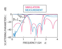
Figure 6 Simulated and measured responses of the fabricated BSF.
Conclusion
A compact wideband BSF, using a coupled stepped impedance hairpin unit and an inner interdigital capacitor, is designed in this article. By tuning the upper transmission line’s characteristic impedance Z2, the capacitances of Cg or the coupling strength of the coupled line, the bandwidth and rejection level of the stopband can be easily controlled. Based on the proposed structure and theoretical analysis, the proposed wideband BSF exhibits three transmission zeros, resulting in a sharp-rejection stopband filtering response. Implementation and test of a microstrip wideband BSF shows a very compact size of 0.022 λg2.
Acknowledgment
The authors wish to acknowledge the support of the National Natural Science Foundation of China under grants (61101052), Zhejiang Provincial Natural Science Foundation under grants (Y1110297) and the Scientific Research Foundation of Zhejiang Sci-Tech University (1004811-Y).
References
- D.M. Pozar, Microwave Engineering, 2nd edition, John Wiley & Sons, New York, NY, 1998.
- J.S. Hong and M.J. Lancaster, Microstrip Filters for RF/Microwave Applications, John Wiley & Sons, New York, NY, 2001, pp. 14–16.
- M.K. Mandal, K. Divyabramham and S. Sanyal, “Compact, Wideband Bandstop Filters with Sharp Rejection Characteristic,” IEEE Microwave and Wireless Components Letters, Vol. 18, No. 10, October 2008, pp. 665–667.
- H.K. Chiou and C.F. Tai, “Dual-band Microstrip Bandstop Filter Using Dual-mode Loop Resonator,” Electronics Letters, Vol. 45, No. 10, May 2009, pp. 507–509.
- M. Hsieh and S. Wang, “Compact and Wideband Microstrip Band-stop Filter,” IEEE Microwave and Wireless Components Letters, Vol. 15, No. 7, July 2005, pp. 472–474.
- M.K. Mandal and S. Sanyal, “Compact Bandstop Filter Using Signal Interference Technique,” Electronics Letters, Vol. 43, No. 2, January 2007, pp. 110–111.
- K. Divyabramham, M.K. Mandal and S. Sanyal, “Sharp-rejection Wideband Bandstop Filters,” IEEE Microwave and Wireless Components Letters, Vol. 18, No. 10, October 2008, pp. 662–664.
- M.A.S. Soriano, G.T. Penalva and E. Bronchalo, “Compact Wide-band Bandstop Filter with Four Transmission Zeros,” IEEE Microwave and Wireless Components Letters, Vol. 20, No. 6, June 2010, pp. 313–315.
- V.K. Velidi, A.B. Guntupalli and S. Sanyal, “Sharp-Rejection Ultra-Wide Bandstop Filters,” IEEE Microwave and Wireless Components Letters, Vol. 19, No. 8, August 2009, pp. 503–505.
- K. Qian and X.H. Tang, “Compact Wideband LTCC Bandstop Filter Using Vertical Coupled-line Units,” Microwave and Optical Technology Letters, Vol. 54, No. 5, May 2012, pp. 1173–1176.
Li-Li Yang is currently working toward the communication engineering bachelor’s degree at the school of Qixin, Zhejiang Sci-Tech University, China. Her research interests include microwave passive circuit design and its applications.
Lin Li obtained his bachelor’s and master’s degrees at the Zhejiang University, China. He received his PhD degree at the Shanghai Jiaotong University, China. He is an associate professor in Zhejiang Sci-Tech University, China. His research interests include microwave passive circuit design and its applications.
Ting Lang is currently working toward the communication engineering bachelor’s degree at the school of Qixin, Zhejiang Sci-Tech University, China. Her research interests include microwave passive circuit design and its applications.
Zhi-Hao Zhang is currently working toward the communication engineering bachelor’s degree at the school of Qixin, Zhejiang Sci-Tech University, China. His research interests include microwave passive circuit design and its applications.
Kai-Yu Zhaois currently working toward the communication engineering bachelor’s degree at the school of Qixin, Zhejiang Sci-Tech University, China. His research interests include microwave components design and applications. His main research fields include microwave reconfigurable filters, microwave antennas and RFID