
Electronic design automation (EDA) is a well-established method for modeling the performance of RF systems for communications products. System level simulation software enables engineers to accurately model and predict system characteristics such as gain, 1 dB compression point (P1dB), noise figure, error vector magnitude (EVM) and adjacent channel power ratio (ACPR). But as wireless networks have evolved, it has become increasingly important to be able to predict the performance of the entire system prior to manufacture, driving the need for accurate models for each device within the system.
For example, in the design of a complex radar system, engineers might design some of the simpler and more specialized components such as filters and antennas themselves, but elect to buy general and/or more complex components such as mixers and amplifiers off the shelf. Obtaining the behavioral models for the designed components is straightforward, since the very process of building them in the EDA environment produces a model. Getting accurate models for the off-the-shelf components, however, can be a challenge.
Typically, in order to obtain a generic device model, the published data from the specification document would be used. While published specifications are a good way to roughly model device behavior, this method is not foolproof. Specification documents are often incomplete and are rarely capable of predicting the performance of modulated signals through the device. A more exact method would be to use instrumentation to extract behavioral models in order to improve the accuracy of RF device models.
Behavioral model extraction is somewhat of an art, requiring experience and detailed knowledge of both instrumentation and the RF device itself. This article will explain two methods for obtaining behavioral RF device models. The first performs simple AM-AM and AM-PM model extraction using instrumentation and is useful for narrowband applications. The second, more complex method, builds a time delay neural network (TDNN) for modeling the behavior of devices that use broadband modulated signals.
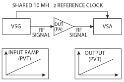
Figure 1 AM-AM/AM-PM can be measured using a VSG and VSA.
Method 1: AM-AM and AM-PM Extraction for PA Behavioral Modeling
Measuring both the output amplitude and phase modulation of an active device, such as an amplifier, is a straightforward process that can be accomplished either with a vector network analyzer (VNA) or the combination of a vector signal generator (VSG) and vector signal analyzer (VSA). This article will focus on the theory, limitations and hardware setup, for performing AM-AM/AM-PM measurements with a VSG and VSA.
The theory behind AM-AM/AM-PMmeasurements is that the behavior of an active device, such as a PA, can be predicted simply by measuring the output amplitude and phaseas a function of input amplitude and phase. In order to measure this response, an RF VSG is used to generate a ramped continuous wave signal through the device under test (DUT). This waveform features a gradually increasing power level, but with constant phase. By using a signal with ramped power, the device can be characterized in both linear and nonlinear operating regions.
As can be seen in Figure 1, a VSA is used to capture the output of the amplifier as I and Q signals. Power and phase are easily calculated from IQ samples using Equations 1 and 2.
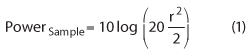
The instantaneous power of each sample can be calculated from I and Q.
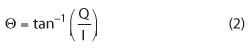
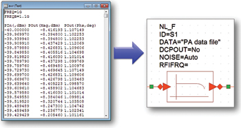
Figure 2 The NL-F element in VSS can use AM-AM/AM-PM measurements to build a simple behavioral model of an RF amplifier.
The instantaneous phase is the inverse tangent of Q/I.Once AM-AM/AM-PMare measured with a VSA, this data can be directly imported into the system simulation environment to model the behavior of active RF components. For example, as can be seen in Figure 2, the NL_F element in AWR’s Visual System Simulator™ (VSS) simulation environment natively uses AM-AM/AM-PM measurements to construct a behavioral model of an RF device.
Benefits and Limitations of AM-AM/AM-PM
While AM-AM/AM-PMextraction is a useful modeling technique, due to the simplicity of the extraction process, this method does involve inherent limitations in some applications. As observed in the previous section, using AM-AM/AM-PMas a behavioral modeling technique assumes that the magnitude and phase at the output of a device can be directly predicted from the magnitude and phase of a signal at the device input. While this assumption is reasonable for narrowband signals or memoryless RF devices, this cannot be assumed for all cases.
For example, active devices such as a PA will often exhibit memory effects. In these conditions,
the output signal magnitude and phase are also functions of the input signal history.
In general, continuous-wave (CW)-based modelextraction techniques are most effective at predicting device behavior in the simulation environment, when they are used on relatively narrowband signals where the effects of memory are much less. As a result, alternative methods of model extraction should be considered when creating a model that will be used to simulate the behavior of a broadband signal.
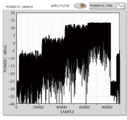
Figure 3 A modulated signal with content at various power levels is used to train the TDNN.
Method 2: Building a TDNN for PA Behavioral Modeling
The second method for extracting behavioral models discussed in this article is to build a TDNN. This method is a good technique for modeling the behavior of a device using broadband modulated signals. TDNNs use intelligent signal processing to represent each output IQ sample as a nonlinear combination of the present IQ input and previous IQ inputs in time. Using this mechanism, a TDNN is able to inherently represent the memory behavior of an RF PA.
The process of using TDNNs to model active RF devices requires us to “train” the TDNN, using a series of input and output IQ samples. As a general rule, the ability of the TDNN to predict the behavior of the RF device is heavily influenced by how closely the characteristics of the training signals mirror the characteristics of the signals being modeled. As a result, the first step in extracting a TDNN model is to drive the active device with a modulated signal and capture the output IQ samples with an RF VSA. Both the input IQ waveform to the device and the IQ output can then be used to train the TDNN.
As shown in Figure 3, one technique used to produce a highly accurate TDNN model is to capture IQ samples at a wide range of power levels. The figure shows the “power versus time” profile of the output of a PA. In this particular case, the input waveform to the PA is a modulated signal that is stepped over various power levels. This technique lets designers capture device behavior at a much broader range of power levels, enabling them to build a more accurate TDNN model.
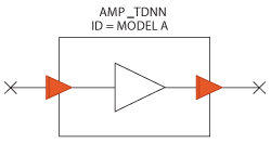
Figure 4 The TDNN model is represented by an element in the system diagram that can be connected to other RF components.
In order to build a TDNN behavioral model, captured IQ samples (along with the original input waveform) can be fed into a TDNN model creation wizard within the simulation software environment. AWR’s VSS software, for example, includes a wizard that uses sampled IQ data to both train and validate the TDNN. The output of the wizard is a TDNN model element (shown in Figure 4) that can be used in future system simulations.
Proving Model Accuracy
Once a model has been extracted and is available in the simulation environment, the final step is to validate the model’s ability to predict the performance of the actual device. A basic way to validate a model is to compare its performance versus the actual device for modulation quality measurements, such as EVM, and spectral measurements, such as ACPR. In addition, for models that are not constructed from AM-AM/AM-PMmeasurements (such as TDNN), it is useful to compare the model’s AM-AM/AM-PMwith the actual device.
When comparing EVM and ACPR results between the model and actual device, it is critical to ensure that the waveform used to drive each device (either actual or model) is identical. In addition, on the measurement side, it is also important to ensure that identical measurement algorithms are used to compute EVM and ACPR to eliminate the potential for differences in measurement algorithm implementation.

Figure 5 The same LabVIEW signal creation and analysis routines can be used in both the simulation environment and with physical measurements.
The system diagram in Figure 5 shows a method for ensuring algorithm uniformity that uses measurement routines based on National Instruments (NI) LabVIEW system design software that are within the AWR VSS environment. In this scenario, one can use LabVIEW generation and analysis toolkits for wireless standards such as WCDMA, LTE and 802.11. As shown in the figure, the LabVIEW code can be directly used within the VSS system diagram to perform measurements on simulation models.
Using the techniques just described, it is easy to assess the model’s ability to predict RF behavior, by comparing its performance to the real device. Figure 6 shows the spectrum profile of an LTE signal being generated through a TDNN model. It can be seen that the spectrum profile of the model matches very closely the actual signal output. This indicates, as evidenced by the spectral regrowth, that the model is able to reasonably predict the amplifier’s performance in a nonlinear region.
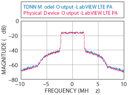
Figure 6 Spectrum profile of a TDNN model vs. the performance of the physical device.
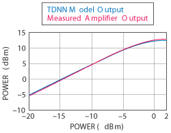
Figure 7 The AM-AM response of the TDNN model closely correlates with the actual device performance.
Finally, in Figure 7, the AM-AMperformance of the TDNN model is compared with the behavior of the measuredamplifier itself. The “modeled” AM-AMmeasurements are made by using a virtual network analyzer in the simulation environment. The figure illustrates that the TDNN model is able to predict the appropriate gain and compression point of the physical device.
Conclusion
While there are many ways to produce a device model for use in the communications system simulation environment, model extraction using test and measurement equipment is a useful and accurate way to build device models to predict system performance. For systems using narrowband signals, simple methods such as AM-AM/AM-PM measurements are often sufficient to build a simulation model. For capturing memory effects on broadband signals, more complex methods like TDNN modeling are a convenient and more accurate way to build a device model and the model’s ability to predict the performance of the actual device can be validated using a hardware/software solution, such as measurement routines based on National Instruments (NI) LabVIEW system design software that are within the AWR VSS environment.
Using either the simple AM-AM/AM-PM or TDNN method, this article demonstrates that models extracted with instrumentation are often able to very efficiently and accurately predict the performance of the RF device itself, saving design time and ultimately producing higher performing communications products.