
VHF OCXOs are widely used as ‘master oscillators’ in signal sources and frequency synthesizers, where the output frequencies are derived by techniques including multiplication, PLL, DDS, etc. In low-noise sources, the phase noise floor is typically limited by the multiplied OCXO.
Pascall’s XMN (crystal multiplied by N) series combines an OCXO with frequency multipliers, bandpass filters and amplifiers to provide a fixed-frequency output with low phase noise, in the range of 200 MHz to 3 GHz. The XMNP adds a phase-locked loop to enable the OCXO to be locked to an external reference.
Design
It is well known that multiplying frequency by N increases phase noise by 20 log(N) dB. However, achieving this theoretical ideal is easier said than done, particularly when the fundamental signal has a very low noise floor.
Active multipliers almost inevitably have a high noise figure and therefore degrade the phase noise floor at the input frequency. With passive multiplication, the added noise is mostly determined by the signal level at the output frequency and the noise figure of the following amplifier. An inappropriate choice of multiplier or amplifier devices can also increase the flicker noise.
In the XMN, the nonlinear resistance of Schottky diodes is used to generate harmonics, with the multiplier tuned for the required input and output frequencies. The conversion loss varies relatively little with temperature and input power, and the circuit is easily tuned to different frequencies.
Two multiplier configurations are used to produce odd and even harmonics, respectively. All multiples up to 10 can be generated – typically up to 1.3 GHz, depending on the fundamental frequency. The first stage is followed, if necessary, by a further doubler or tripler, to generate frequencies up to 3 GHz.
The XMN is available with either electrical tuning (0 to +10 V, positive or negative slope) or mechanical tuning by means of a multi-turn potentiometer. The XMNP phase-locked variant includes RF and reference dividers. This provides flexibility in the choice of customer-specified reference frequency, which may be as high as the oscillator frequency. If a reference signal is detected, the XMNP automatically locks to it. In the absence of a reference it behaves as an XMN, with the frequency set by a multi-turn potentiometer.
All variants provide a supplementary output at the fundamental frequency. This may typically be used to generate intermediate frequencies in a synthesizer, or to lock the XMN in a customer-designed PLL.
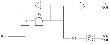
Figure 1 Simplified block diagram of XMNP.
The design allows customers to specify the oscillator frequency (up to 160 MHz) as well as the multiplied frequency. For example,
1 GHz can be generated from 100 MHz × 10, 111.111 MHz × 9, 125 MHz × 8 or 142.857 MHz × 7. This flexibility can facilitate frequency planning for a particular application, or alternatively can be used to optimize the phase noise. Lower multiplication ratios give lower noise floor. On the other hand, choosing a lower oscillator frequency will reduce the close-in phase noise.
The basic package size is 101.6 × 57.2 × 20.3 mm for the XMN and 101.6 × 87.5 × 20.3 mm for the XMNP. This typically allows for all multiples up to 10. If an extra multiplication stage is needed, for 3 GHz output for example, the width increases to 81.5 mm or 111.8 mm for the XMN and XMNP, respectively. The standard supply voltage is +12 V, with +15 V available as an option. Figure 1 shows a simplified block diagram of the XMNP phase-locked signal source.
Performance
The main criterion when developing the XMN was that the phase noise should be as low as possible. In this regard, integrating oscillator, multiplier, amplifiers and filters into a single unit can give better performance than a building-block approach, as the individual sections can be optimized to work with each other.
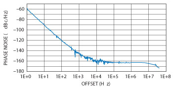
Figure 2 1.2 GHz XM10 phase noise.
The phase noise floor at the multiplied output is typically equivalent to –183 dBc/Hz at the oscillator’s frequency. For example, the phase noise floor of an 840 MHz output derived from 120 MHz is typically –166 dBc/Hz.
Close-to-carrier phase noise is similar to that of Pascall’s OCXO and OCXOF oscillators. Internal regulators are used to reduce the effect of supply noise and ripple. Particular care has been taken to minimize low-frequency noise on the oscillator supply, ensuring that even at 1 Hz offset, the full performance offered by low-noise crystals is realized.
Figure 2 shows the phase noise at the 1.2 GHz output of an XM10 (120 MHz × 10), measured with an Agilent E5052B signal source analyzer. Output power at both fundamental and multiplied frequencies is 13 dBm, with sub-harmonics and spurious products <–80 dBc.
The XMNP operates with reference input levels from –3 to +16 dBm, which makes it very easy to incorporate into customers’ applications. The PLL bandwidth is ≤1 Hz, giving it high rejection of noise and spurs on the reference signal.
Applications
The low phase noise and spurious outputs of the XMN and XMNP make them ideal building blocks for high performance synthesizer designs. Other uses include satellite ground stations, phase noise test systems, and EW systems and scientific research. In certain applications, the XMN/XMNP may provide a practical alternative to a SAW oscillator, offering improved close-to-carrier phase noise and flexibility of output frequency without incurring the development cost of a non-standard SAW resonator.
Pascall Electronics Ltd.,
Ryde, Isle of Wight, UK
+44 (0)1983 817300,
enquiries@pascall.co.uk
www.pascall.co.uk