

Comprehensive on-site testing of base stations using real-world scenarios, both at initial installation and then during ongoing maintenance, plays a vital role in preventing and solving performance problems before they impact subscribers. Thorough independent testing gives operators greater confidence in the quality of the deployed network. Poorly performing base stations have a significant impact on the quality of service experienced by users of the higher data rate services available on EDGE and 3G networks. Whether this is caused by incorrect installation, a gradual degradation in performance, or complete failure of a particular module, the end result is that subscribers will suffer poor performance and will be less satisfied with their service provider.
In order to avoid scenarios of this type Aeroflex’s RIWS 6413A base station test set has been developed. Its concept is the same as the company’s 6113 GSM base station tester, which is used by GSM operators throughout the world. However, the 6413A is aimed at operators’ and infrastructure vendors’ field technicians installing and maintaining 3G Node Bs. It is designed to allow technicians to perform a complete set of transmitter and receiver measurements that will give confidence that the Node B under test is working correctly, and, if not, to give sufficient information to enable faulty modules to be replaced or repaired. The 6413A will support the measurements shown in Table 1, with others to be added on an ongoing basis.

Mobile phone operators are placing increased emphasis on test equipment that is easy to use and will withstand the rigors of field operation. The 6413A has been designed with this in mind and accordingly incorporates a number of features in both the user interface and technical performance. To make operation as simple and as intuitive as possible, the instrument contains an embedded PC running the Microsoft Windows XP operating system and incorporates a touch-screen display (as shown in Figure 1).
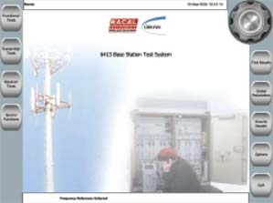
Fig. 1 The front panel display utilizing touch-screen controls.
A particular feature is the ‘one button test’ that enables an automated sequence to be set up in advance that can then be run repeatedly at the press of a single on-site button. Other features include the ability to measure power levels up to +46 dBm. This removes the need to use attenuators between the Node B output and the test equipment input, thus reducing the likelihood of expensive repairs as a result of mistakenly overloading the input.
Receiver Testing
Although some base stations incorporate a small amount of built-in test equipment, and there are solutions available for checking transmitter characteristics, an area that is consistently overlooked is the adequate testing of the complete base station receiver path from the RF input to the Iub connection to the Radio Network Controller (RNC).
If the receiver is failing to perform to specification, the operator takes the risk that their subscribers will experience some or all of the following problems:
• An increase in dropped calls at the limits of cells due to poor sensitivity.
• An increase in dropped calls throughout the cell because of poor signal quality.
• The inability to use revenue generating higher data rate services because of poor signal quality.
The ability to make receiver measurements is a key feature and differentiator of the 6413A. Although making receiver measurements sounds straightforward, there is actually considerable complexity involved. Figure 2 shows the test setup.

Fig. 2 Receiver measurements test setup.
To make receiver measurements it is necessary to emulate the Radio Network Controller so that the Node B acts as if it is connected to a real network. The 6413A communicates with the Node B via the Iub link, sending it messages to operate in a particular manner. The instrument then generates an uplink DCH channel containing a pseudorandom bit sequence (PRBS). This PRBS is, in turn, transmitted to the tester’s RNC emulator via the Iub interface, decoded and the bit error rate (BER) determined. Although this sounds straightforward, there are a number of issues that need to be addressed in the design:
• Whereas many elements of the Iub interface are standardized, there are some elements that are manufacturer, Node B model, or even Node B software version specific. This requires the instrument to have software that can be adapted to all of these conditions.
• The ATM protocols used for the Iub interface are complex to implement and decode so the 6413A incorporates a Network Interface Module to manage the ATM protocols and physical interfaces (E1, T1 and STM-1).
• Decoding of the Iub information to extract the original PRBS from within the DCH.
Figure 3 shows a typical receiver measurement result.

Fig. 3 A typical receiver BER measurement result.
Future Proofing
Today’s 3G networks are being rolled out using the R99 version of the 3G standards. However, R5 is likely to appear within the next year, while network operators will continue to operate their GSM networks for some future time. The 6413A makes use of powerful baseband processing and software-defined radio techniques to ensure maximum flexibility and the future ability to add GSM, GPRS, EDGE and FDD R5 with a simple upgrade. In addition, the RF transceiver is designed to cover all GSM and UMTS frequency bands. The Network Interface Module has also been designed to manage the changes in the Iub protocol introduced by R5 as well as the A-bis control requirements for testing GSM base stations.
Conclusion
The 6413A has been designed specifically to withstand the rigors of field operation, while at the same time being easy to use and providing full functionality. In particular, the instrument contains an embedded PC running the Microsoft Windows XP operating system, ‘one button test’ operation and a touch-screen display. The facility for receiver measurement is a key function and by the very nature of its potential applications future proofing has been a primary consideration during its development — through a simple update there is the facility to add GSM, GPRS, EDGE and FDD R5 when required, thus offering the flexibility and practicality that is paramount for such instruments.
Racal Instruments Wireless Solutions,
an Aeroflex company,
Slough, UK
+44 1628 604455
or e-mail: riws@aeroflex.com.