
Ultra-wideband (UWB) radio technology enables several important applications, including ground penetrating radar, imaging, location tracking and low cost, short-range communications. With the recent Federal Communications Commission (FCC) approval of rules for operation of UWB devices under Part 15, devices aimed at these, and possibly other, applications will soon be on the market. This article provides a summary of the newly adopted rules and also explores some of the possible interactions between UWB and other wireless communications systems.
Ultra-wideband technology uses extremely short pulses of electromagnetic energy (on the order of a few nano-seconds) that, in the frequency domain, translate to very wide bandwidths (spanning over several gigahertz of spectrum). This is somewhat reminiscent of the spark-gap generators used in the early 1900s during the pioneering days of radio. However, modern UWB transmitters use very specific pulse shaping techniques and highly accurate timing to facilitate imaging and communications. An overview of the history of UWB and many of the issues facing researchers, systems designers and regulators may be found in Barrett.1,2 Also, the first IEEE conference on UWB was held recently and included sessions on several facets of UWB, including signal processing, device technology and applications.3 The conference was highlighted by a presentation delivered by Edmond Thomas, chief of the FCC's Office of Engineering and Technology, who gave an overview of the UWB rulemaking proceeding and the newly adopted rules.4
The New Part 15 Rules
After several years of debate and over 900 documents filed in the Commission's docket on UWB, the FCC adopted the rules for Part 15 operation of UWB devices on February 14, 2002 (these were officially published in the Federal Register on May 16, 2002). The full text of the FCC's Report and Order can be found on the FCC Web site at http://hraunfoss.fcc.gov/edocs_public/attachmatch/FCC-02-48A1.pdf, while the most recent version of the Part 15 rules can be found at www.fcc.gov/oet/info/rules/.
The emission levels adopted in the new rules are based on the existing levels defined in Part 15.209 for unlicensed devices classified as intentional radiators. The limits are given in terms of electric field intensity at a distance of three meters from the device along with an appropriate measurement bandwidth. The equivalent effective isotropic radiated power (EIRP) level can be found using

or, equivalently,

Expressing E in µv/m, this reduces further to
EIRP (dBm) = 20log(E) -95.23
If E is expressed in dBmv/m, the conversion to EIRP (assuming a distance of 3 m) may be performed by simply subtracting 95.23.
It should be noted that for frequencies above 960 MHz, the emission limits are to be measured using an averaging detector with a resolution bandwidth of 1 MHz. For frequencies below 960 MHz, the measurements are to be performed using a quasi-peak detector as defined in CISPR-16.5 In this case, the measurement bandwidth (6 dB bandwidth) is specified as 120 kHz. The limits and measurement parameters given in Part 15.209 are summarized in Table 1 . Note that the Part 15 limits are given in terms of the electric field, and when converting to other emission bandwidths the appropriate conversion factor depends on whether the desired quantity is an average or peak value. For peak emission limits the appropriate conversion factor is 20 log(BW) and for average limits the appropriate factor is 10 log(BW), where BW is the ratio of the two bandwidths.
The new Part 15 specifications for UWB devices (Subpart F: 15.501-15.525) include several definitions for certain aspects of UWB emissions and specifies four broad classes of UWB devices. In general, a UWB transmitter is defined as a transmitter with a fractional bandwidth greater than or equal to 0.2 or with a UWB bandwidth greater than or equal to 500 MHz. Of particular interest is the definition of UWB bandwidth: UWB bandwidth is the frequency band bounded by the points that are 10 dB below the highest radiated emission, as based on the complete transmission system including the antenna. The upper boundary is designated fH and the lower boundary is designated fL (also, the frequency at which the highest radiated emission occurs is designated fM and must be contained within this bandwidth).
The UWB devices are defined as imaging systems, vehicular radar systems, indoor systems and hand-held systems. The specifications for each class of device are summarized below.
|
Table 1 | ||||
|
Frequency |
E-field Limit |
EIRP |
Detector, |
Average EIRP |
|
30 to 88 |
100 at 3 m |
-55.2 |
Quasi-peak 120 kHz (6 dB) |
-46.0 |
|
88 to 216 |
150 at 3 m |
-51.7 |
Quasi-peak 120 kHz (6 dB) |
-42.5 |
|
216 to 960 |
200 at 3 m |
-49.2 |
Quasi-peak 120 kHz (6 dB) |
-40.0 |
|
>960 |
500 at 3m |
-41.3 |
Average 1 MHz |
-41.3 |
Imaging Systems
This class is further divided into (1) low frequency imaging systems, (2) mid-frequency imaging systems and (3) high frequency imaging systems. In general, imaging systems can be operated by law enforcement and emergency personnel, research institutions, mining and constructions companies, etc. Operation of these devices requires coordination, as described in Part 15.525, and the device must have a manually operated or remote control switch that de-activates the transmitter within 10 seconds.
1. Low Frequency Imaging Systems: The UWB bandwidth must be below 960 MHz and the emissions below 960 MHz must not exceed the levels in Part 15.209. Above 960 MHz lower limits apply. Also, the peak power must not exceed 0 dBm EIRP in a 50 MHz bandwidth centered on the frequency of the highest emission, fM.
2. Mid-frequency Imaging Systems: The UWB bandwidth must be contained between 1990 MHz and 10.6 GHz. In this band the EIRP limit is -41.3 dBm/MHz. The limits below 960 MHz are given in 15.209 and the peak power must not exceed 0 dBm EIRP in a 50 MHz bandwidth centered on the frequency of the highest emission, fM.
3. High Frequency Imaging Systems: The UWB bandwidth must be contained between 3.1 and 10.6 GHz. In this band the EIRP limit is -41.3 dBm/MHz and lower limits apply in other band segments. Also, the peak power must not exceed 0 dBm EIRP in a 50 MHz bandwidth centered on the frequency of the highest emission, fM.
Vehicular Radar Systems
These are field disturbance sensors that operate only while the vehicle is operating (that is engine running) and must only be activated for specific reasons including starting the vehicle, engaging the turn signals, etc. The UWB bandwidth must be contained between 22 and 29 GHz, and the center frequency, fC, must be above 24.075 GHz. In this band the EIRP limit is -41.3 dBm/MHz and lower limits apply in other band segments. Additional limits apply to emissions that appear at 30°, or greater, above the horizontal plane. Also, the peak power must not exceed 0 dBm EIRP in a 50 MHz bandwidth centered on the frequency of the highest emission, fM.
Indoor Systems
These devices are intended solely for indoor operation and must operate with a fixed indoor infrastructure. The use of outdoor antennas is prohibited as is intentionally directing the transmission outside of a building. The UWB bandwidth must be contained between 3.1 and 10.6 GHz, and the EIRP limit is -41.3 dBm/MHz in this band. Lower limits apply in other band segments, as shown in Figure 1 . Also, the peak power must not exceed 0 dBm EIRP in a 50 MHz bandwidth centered on the frequency of the highest emission, fM.
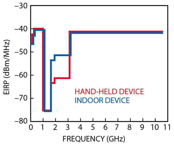
Hand-held Systems
These devices must be hand-held in nature, do not employ a fixed infrastructure and must include antennas mounted on the device itself. The UWB bandwidth must be contained between 3.1 and 10.6 GHz, and the EIRP limit is -41.3 dBm/MHz in this band. Lower limits apply in other band segments. Also, the peak power must not exceed 0 dBm EIRP in a 50 MHz bandwidth centered on the frequency of the highest emission, fM.
A few additional rules are included that apply to all classes of UWB devices. No UWB devices may be employed in toys, although there does not seem to be any official definition of a toy. Also, operation on an aircraft, a ship, or a satellite is prohibited.
Impact of UWB Emissions on Other Receivers
The broadband nature of UWB transmissions means that UWB emissions will be received by other conventional, narrowband RF systems as well as other UWB systems. Since UWB devices will be operating on an unlicensed basis, it is impossible to predict when or where a UWB device could be used. Of particular interest is the interaction of UWB devices with cellular and PCS receivers. GPS, PCS and the 1990 MHz to 3.1 GHz bands were given some measure of protection in the new Part 15 rules as the limits in these bands are at least 10 dB below the existing Part 15 limit. The exact limits for these bands depend on the type of UWB device in use. Note that the existing Part 15.209 limits have been retained in all cases for devices operating below 960 MHz, including the cellular bands (824 to 849 MHz and 869 to 894 MHz).

To evaluate the potential impact of UWB emissions on other receivers, consider devices that are allowed to transmit in the cellular mobile receive band (f = 880 MHz) and the PCS mobile receive band (f = 1960 MHz). Assuming that these devices are transmitting at the newly adopted EIRP levels of -49 dBm/120 kHz at 880 MHz, -53.3 dBm/MHz at 1960 MHz and -63.3 dBm/MHz at 1960 MHz, the power spectral density (PSD) levels as a function of distance are shown in Figure 2 . Note that for a UWB device that emits energy at 1960 MHz the levels given are the EIRP levels adopted for indoor and hand-held UWB operation, respectively. The results shown assume isotropic transmit and receive antennas, and free-space propagation conditions (path loss exponent = 2). In some cases, walls and other obstructions may reduce the received power and a higher path loss exponent would be appropriate. In other cases, however, it should be expected that no obstructions exist and free-space propagation is the appropriate model, especially when in close proximity to the transmitting device.
Using the PSD data, it is possible to determine the impact of UWB devices on other conventional receivers. For example, consider a typical GSM mobile operating in the 1900 MHz band. The noise floor is determined by the thermal noise in the 200 kHz bandwidth plus the noise figure, such that
Noise floor =
-174 dBm/Hz + 53 dBHz + 8 dB =
-113 dBm (in 200 kHz bandwidth)
assuming that the mobile receiver has a noise figure of 8 dB. One figure of merit commonly used to assess interference issues is to determine the point at which the interference will cause an effective rise in the noise floor of 1 dB. This is also the point at which the interference level is 6 dB below the current noise floor. Using the noise floor given above, the GSM mobile phone will exhibit a 1 dB increase in the noise floor at an interference level of -119 dBm/200 kHz. At 1960 MHz, the measurement bandwidth is 1 MHz, and accounting for the difference in bandwidths the equivalent average power level is

Using the PSD data, this signal level occurs at a distance of approximately 10 m from the indoor UWB device and at approximately 3 m from a hand-held UWB device. Thus, at 1960 MHz a GSM receiver could experience interference if it is within 10 m (~33 ft.) of an indoor UWB transmitter or within 3 m (~10ft) of a hand-held UWB device.
As another example, consider a TDMA (TIA/EIA-136) mobile station receiver operating at 880 MHz. In this case the system noise floor is given by
Noise floor =
-174 dBm/Hz + 45 dBHz + 8 dB =
-121 dBm (in 30 kHz bandwidth)
again assuming the receiver noise figure of 8 dB. In this case, the receiver will exhibit a 1 dB rise in the noise floor at an interference level of -127 dBm/30 kHz. Accounting for the difference in bandwidth, the average power is

and this level occurs at a distance of approximately 105 m (~340 ft.) from the UWB transmitter. In this case, a TDMA receiver could experience interference if a UWB device is transmitting within 340 ft. of the receiver, assuming free-space propagation. Note that in both examples, a single UWB device was emitting, free-space propagation conditions were assumed and the device antennas were assumed to be isotropic with matched polarization.
While the examples for GSM and TDMA mobile station receivers indicate that interference from UWB transmitters is certainly possible, the exact nature of the interference depends on several factors including pulse repetition frequency (PRF) of the UWB signal, orientation of the transmitter and receiver antennas, surrounding walls and other obstructions. If the path loss exponent is increased to 4 to model a much worse propagation environment, the distances given above for GSM and TDMA reduce to approximately 1 and 5 ft., respectively. Additional results for other path loss exponents are shown in Table 2 . In each case, as the path loss exponent increases, the distance at which the victim receiver would experience a 1 dB "noise rise" is reduced. Certainly, there will be some scenarios when walls, other structures and even vegetation will reduce the effects of UWB emissions on other receivers. However, there will also be instances where propagation losses are lower and interference from UWB devices could be a concern even at distances of several meters or tens of meters.
|
Table 2 | ||||
|
System, |
Receive |
UWB Device |
Path |
Distance for |
|
TDMA, |
880 |
-49.2 dBm/ |
2 |
105 (~340 ft.) |
|
GSM, |
1960 |
-53.3 dBm/MHz |
2 |
10.5 (~34 ft.) |
Co-location of UWB Transmitters with Other Transmitters/Receivers
In many instances, it may be necessary or desirable to operate a UWB device in close proximity to a conventional transmitter/receiver. For example, one potential application for UWB devices is low cost, short-range wireless networking systems similar to Bluetooth or 802.11 WLAN. It is easy to envision that these types of UWB devices could be built into mobile phones or other wireless communications devices. For these types of applications, it is necessary for each receiver to be able to operate properly while the other transmitters are active.
For mobile phones, specifications already exist for this type of transmitter/receiver coupling. These signal levels should also apply to other transmitters that may be co-located on the same piece of equipment. The levels specified for transmitted power in the receive bandwidth for GSM6 and TDMA7 are shown in Table 3 . As can be seen from the data, the levels adopted in the 1930 to 1990 MHz band are consistent, on an average level, with the levels adopted for hand-held UWB devices. However, the levels adopted for indoor UWB devices and all of the limits below 960 MHz are still significantly higher than the limits defined for GSM and TDMA receivers. Thus, for these types of applications it may be necessary to limit the UWB EIRP in the cellular and PCS receive bands.
|
Table 3 | ||||
|
Technology |
Frequency Range |
Emission Level |
Average |
Part 15 |
|
TDMA |
869 to 894 |
-80 dBm, 30 kHz |
-64.8 |
-40.0 |
|
GSM |
869 to 894 |
-79 dBm, 100 kHz |
-69.0 |
-40.0 |
Conclusion
After years of debate, the FCC recently adopted a new set of rules to allow the operation of UWB devices. Within the next few months, it is anticipated that UWB products will be approved under the new rules and appear on the market to address several different applications. Through the course of the rulemaking proceeding, the majority of the debate on UWB centered around the question of whether interference into conventional receivers will become a problem. Even with the adoption of new rules, the debate on interference and other regulatory issues surrounding UWB will continue. Already, several companies and industry groups have made filings with the FCC asking for reconsideration of the new rules.
As with all radio transmitters, the potential for interference depends on many things, including when and where the device is used, transmit power level, number of devices transmitting, pulse repetition frequency, and direction of the emitted signal. Although the Part 15 rules now allow for operation of UWB devices, testing on the interactions of UWB with other wireless systems will continue. According to the FCC's Office of Engineering and Technology,4 a testing program will begin this year to assess the effects of UWB and to also understand the existing noise/interference levels in today's radio environment. As described, there is a potential for interference into existing TDMA and GSM receivers. Future testing should certainly include the effects of UWB on these technologies as well as other 2G and 3G wireless systems.
References
1. T.W. Barrett, "History of Ultra Wideband Communications and Radar: Part 1, UWB Communications," Microwave Journal , Vol. 44, No. 1, January 2001, pp. 22-56.
2. T.W. Barrett, "History of Ultra Wideband Communications and Radar: Part 2, UWB Radar and Sensors," Microwave Journal , Vol. 44, No. 2, February 2001, pp. 22-52.
3. IEEE UWBST 2002 (www.uwbst2002.com), Baltimore, MD, May 20-23, 2002.
4. E. Thomas, "Walk Don't Run - The First Step in Authorizing Ultra-wideband Technology," presented at the IEEE UWBST 2002, Baltimore, MD, May 20-23, 2002. Available at: www.uwbst2002.com/pdf/PlenarySession_Thomas.ppt.
5. CISPR-16, "Specification for Radio Disturbance and Immunity Measuring Apparatus and Methods - Part 1: Radio Disturbance and Immunity Measuring Apparatus," October 1999 (www.iec.ch).
6. 3GPP TS 05.05 V8.9.0 (2001-04), Technical Specification Group GSM/EDGE Radio Access Network; Digital Cellular Telecommunications System (Phase 2+); Radio Transmission and Reception (Release 1999).
7. TIA/EIA-136-270-A, "TDMA Mobile Stations Minimum Performance," August 1999.
David Shively is currently a member of the strategic technology group at Cingular Wireless, where he is involved with the evaluation of new technologies as well as regulatory issues related to cellular and PCS. Previously, he held research and development positions with BellSouth Cellular and Hitachi Telecom, where he was involved in the standards development for GPRS/EDGE/ UMTS and cdma2000. From 1988 to 1995, he researched antenna analysis and design at the NASA Langley Research Center. He received his PhD EE degree from Arizona State University and his MS EE degree from Virginia Tech, where he specialized in antenna design, electromagnetics and wireless systems.