
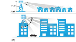
Figure 8 Array complexity depends on the scanning range needed for the deployment: suburban (a) or urban (b).
1D or 2D Scanning
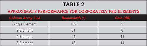
The number of active channels in the array depends on many things. Let’s start by first understanding the azimuth and elevation scanning requirements and whether two-dimensional beamforming is required for a typical FWA deployment or if a lower complexity, one-dimensional (azimuth only) beamforming array is sufficient. This decision impacts the power amplifier (PA). Figure 8 shows two FWA deployment scenarios. In the suburban deployment, the tower heights range from 15 to 25 m and the cell radius is 500 to 1000 m, with an average house height of 10 m. Just as with traditional macro cellular systems, there is no need for fully adaptive elevation scanning. The elevation beam can be focused down by corporately feeding several passive antenna elements, as shown in Figure 9a. This vertically stacked column of radiating elements is designed to minimize radiation above the houses and fill in any nulls along the ground. Further, the gain pattern is designed to increase at relatively the same rate as the path loss. This provides more uniform coverage for both near and far users. The nominal half-power beamwidth can be approximated as 102°/NANT and the array gain by 10log10(NANT) + 5 dBi. With passively combined antennas, the elevation beam pattern is focused and the fixed antenna gain increases, as shown in Table 2. For the suburban FWA deployment, a 13 to 26 degree beamwidth is sufficient, with the passively combined column array from four to eight elements. In the urban scenario, however, the elevation scanning requirements are greater, and systems will be limited to one or two passive elements.
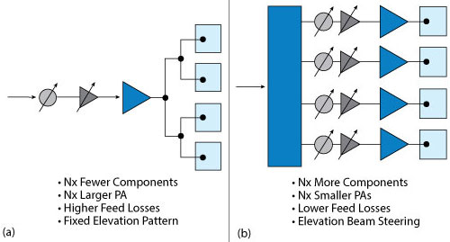
Figure 9 Column-fed (a) and per-element (b) active arrays.
Figure 9b illustrates the per-element active array. Both the per-element and column-fed array architectures have the same antenna gain, but the column-fed array has a fixed elevation beam pattern. The per-element array supports wider scan angles but needs 4x as many PAs, phase shifters and variable gain components for an antenna with four elements. To achieve the same EIRP, the PA driving a column-fed array with four antennas will need to provide at least 4x the output power, which can easily change the semiconductor selection. It is reasonable to assume a suburban BTS will use antennas with 6 to 9 dB higher passive antenna gain compared to an urban deployment. As a result, the phased array needs far fewer active channels to achieve the same EIRP, significantly reducing active component count and integration complexity.
Array Front-End Density
Early mmWave FWA BTS designs used separate, single-polarization transmit and receive antenna arrays, which allowed significantly more board area for components. These designs avoided the additional insertion loss and linearity challenges of a T/R switch. However, a major architecture trend is integrated T/R, dual-polarization arrays (see Figure 10), which is driving RFFE density. The key reason is spatial correlation. Adaptive beamforming performance depends on the ability to calibrate the receive and transmit arrays relative to one another. As such, it is important to integrate the transmit and receive channels for both polarizations, so the array shares a common set of antenna elements and RF paths. The net result is a requirement for the RFFE to have 4x the circuit density of earlier systems.
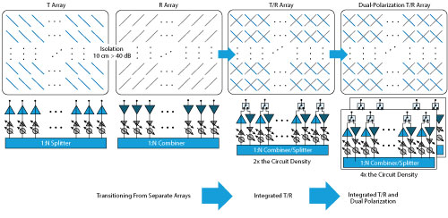
Figure 10 FWA antenna arrays are evolving from separate T and R arrays to integrated T/R arrays with dual polarization.
At mmWave frequencies, the lattice spacing between phased-array elements becomes small, e.g., 3.75 mm at 39 GHz. To minimize feed loss, it is important to locate the front-end components close to the radiating elements. Therefore, it is necessary to shrink the RFFE footprint and integrate multiple functions, either monolithically on the die or within the package, using a multi-chip module. Tiling all these functions in a small area requires either very small PAs, requiring a many-fold increase in array size, or using high-power density technologies like GaN. Further, it is critical to use a semiconductor technology that can withstand high junction temperatures. The reliability of SiGe degrades rapidly above 150°C, but GaN on SiC is rated to 225°C. This 75°C advantage in junction temperature has a large impact on the thermal design, especially for outdoor, passively-cooled phased arrays.
ALL-DIGITAL VS. HYBRID ARRAYS
It was natural for BTS vendors to first explore extending the current, sub-6 GHz, all-digital beamforming, massive MIMO platforms to mmWave. This preserves the basic architecture and the advanced signal processing algorithms for beamformed spatial multiplexing. However, due to the dramatic increase in channel bandwidths offered by mmWave and the need for many active channels, there is a valid concern that the power dissipation and cost of such a system would be prohibitive. Therefore, vendors are exploring hybrid beamformed architectures,5 which allows flexibility between the number of baseband channels and the number of active RF channels. This approach better balances analog beamforming gain and baseband processing. The following sections analyze the two architectures and discuss the RFFE approaches needed for each.