

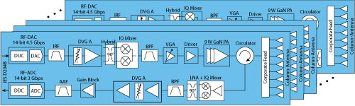
Figure 11 Array design using digital beamforming and commercial, off-the-shelf components.
Digital Beamforming
Assuming large elevation scanning is not required for suburban FWA and a well-designed, column antenna provides gain of up to 14 dBi, we start with a mmWave BTS transceiver design targeting an EIRP of 65 dBm and compute the power consumption using off-the-shelf point-to-point microwave radio components that have been available for years, including a high-power, 28 GHz GaN balanced amplifier. The multi-slat array and transceiver are shown in Figure 11. Assuming circulator and feed-losses of 1.5 dB, the power at the antenna port is 27 dBm. From the following equations, achieving 65 dBm EIRP requires 16 transceivers that, combined, provide 12 dB of digital beamforming gain:
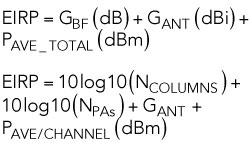
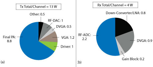
Figure 12 Power dissipation of the transmit (a) and receive (b) chains.
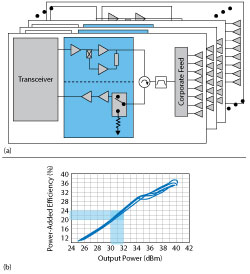
Figure 13 Integrated FEM with symmetric GaN Doherty PA and switch-LNA (a) and PA performance from 27.5 to 29.5 GHz (b).
The power consumption for each transceiver is shown in Figure 12. The total power dissipation (PDISS) at 80 percent transmit duty cycle for all 16 slats will be 220 W per polarization, and a dual-polarized system will require 440 W. For all outdoor tower-top electronics, where passive cooling is required, it is challenging to thermally manage more than 300 W from the RF subsystem, suggesting an all-digital beamforming architecture using today’s off-the-shelf components is impractical.
However, new GaN FEMs are on the horizon to help address this. As shown in Figure 13, the GaN PAs integrated in the FEM apply the tried-and-true Doherty efficiency-boosting technique to mmWave. With Doherty PAs, digital pre-distortion (DPD) is needed; however, the adjacent channel power ratio (ACPR) requirements defined for mmWave bands are significantly more relaxed, enabling a much “lighter” DPD solution. The estimated power dissipation of a 40 dBm PSAT, symmetric, multi-stage Doherty PA can be reduced more than 50 percent. In the above system, this improvement alone drops the total PDISS below 300 W. Combined with power savings from next-generation RF-sampling digital-to-analog and analog-to-digital converters, advancement in mmWave CMOS transceivers and increased levels of small-signal integration, it will not be long before we see more all-digital beamforming solutions being deployed.
Hybrid Beamforming
The basic block diagram for a hybrid beamforming active array is shown in Figure 14. Here, N baseband channels are driving RF analog beamformers, which divide the signal M-ways and provide discrete phase and amplitude control. FEMs drive each M-element subarray panel. The number of baseband paths and subarray panels is determined by the minimum number of spatial streams or beams that are needed. The number of beamformer branches and elements in each subarray panel is a function of the targeted EIRP and G/NF. While a popular design ratio is to have one baseband path for every 16 to 64 active elements, it really depends on the deployment scenario. For example, with a hot-spot small cell (or on the CPE terminal side), a 1:16 ratio single panel is appropriate. A macro BTS would have two to four subarray panels with 64 active elements, where each panel is dual-polarized, totaling four to eight baseband paths and 256 to 512 active elements. The digital and analog beamforming work together, to maximize coverage or independently, to provide spatially separated beams to multiple users.
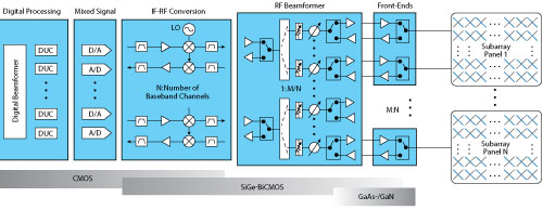
Figure 14 Active array using hybrid beamforming.
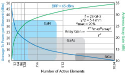
Figure 15 Optimum RFFE technology vs. array size.
There is an important trade unfolding, whether SiGe front-ends can provide sufficient output power and efficiency to avoid the need for higher performance III-V technology like GaAs or GaN. With good packaging and integration, both approaches can meet the tight antenna lattice-spacing requirements.
FRONT-END SEMICONDUCTOR CHOICES
The technology choice for the RFFE depends on the EIRP and G/NF requirements of the system. Both are a function of beamforming gain, which is a function of the array size. To illustrate this, Figure 15 shows the average PA power (PAVE) per channel needed as a function of array size and antenna gain for a uniform rectangular array delivering 65 dBm EIRP. The graph is overlaid with an indication of the power ranges best suited for each semiconductor technology. The limits were set based on benchmarks of each technology, avoiding exotic power-combining or methods that degrade component reliability or efficiency. As array size gets large (more than 512 active elements), the power per element becomes small enough to allow SiGe, which can be integrated into the core beamformer RFIC. In contrast, by using GaN for the front-end, the same EIRP can be achieved with 8 to 16x fewer channels.
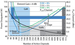
Figure 16 System power dissipation vs. array size and EVM for 64 dBm EIRP.
System Power Dissipation
For an array delivering 64 dBm EIRP, Figure 16 shows an analysis of the total PDISS of the beamformer plus the front-end as a function of the number of active elements in each subarray panel. The PDISS is shown for several error vector magnitude (EVM) levels, since the EVM determines the power back-off and efficiency achieved by the front-end. We assume each beamformer branch consumes 190 mW, which is the typical power consumption of core beamformers in the market.6 The system on the far right of the figure represents an all-SiGe solution with 512 elements, with an output power per element of 2 dBm and consuming approximately 100 W. Moving left, the number of elements decreases, the PAVE per channel increases and PDISS is optimized to a point where beamforming gain starts to roll off sharply, and the PDISS to maintain the EIRP rapidly increases. The small steps in the dissipation curves represent where the front-end transitions from a single stage to two-stage and three-stage designs to provide sufficient gain. As stages are added, the efficiency drops with the increase in power dissipation.
Designing to optimize system PDISS without regarding complexity or cost, an array of about 128 elements with a two-stage, 14 dBm output PA (24 dBm P1dB) is the best choice. However, if we strive to optimize cost, complexity and yield for a PDISS budget of under 100 W, the optimum selection is the range of 48 to 64 active channels using a three-stage GaN PA with an average output power of 20 to 23 dBm, depending on the EVM target. The trends shown in Figure 16 are less a function of PA efficiency and more a function of beamformer inefficiency. In other words, the choice to increase array size 8x to allow an all-SiGe solution comes with a penalty, given that the input signal is divided many more ways and requires linearly biased, power consuming devices to amplify the signal back up.