
After decades of remaining dormant for want of suitable applications, millimeter wave systems operating at 60 GHz are finally appearing. Short range, very high data rate wireless links for cellular backhaul, multi-building hops, video surveillance and airport security screening are now joining the few services already in operation. To aid in the development of systems for the unlicensed 57 to 64 GHz band, Pasternack Enterprises in collaboration with Vubiq Inc., has developed the PEM003-KIT Transmit/Receive Development System, which lets designers create transmit – receive paths at varying distances and change key parameters to verify and optimize the performance of their designs.
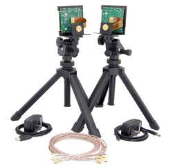
The PEM003-KIT consists of four primary hardware components: transmitter and receiver PC boards (see Figure 1) and WR15 waveguide antenna modules that together allow a transmission – reception path to be created. The developer can experiment with the characteristics of the path using supplied Windows-based software that acts as a control panel and enables system monitoring, configuration and experimentation (see Figure 2).
Two WR15 antenna modules are available. The first covers a board-to-board communication distance of 30 to 50 m, with 20 dBi of gain; the second covers distances between 200 and 300 m, with 34 dBi gain.
The control processors on the development system boards communicate with the software on the PC via a USB connection, which also powers the boards (AC adapters are provided for both boards as well). Baseband signals are routed via a high speed connector on the rear of each board. Optional expansion boards provide a transition to a set of MCX coaxial connectors for the baseband and external reference clock signals.
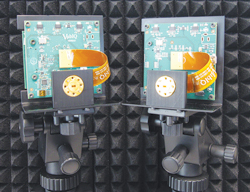
Figure 1 The PEM003-KIT's primary components are the transmitter and receiver PC boards and WR15 waveguide antenna modules, shown mounted on their tripods.
In a typical scenario, the transmitter’s baseband source, such as an arbitrary waveform generator (AWG), creates two channels of vector (I and Q) or standard modulation formats such as BPSK or QPSK. The AWG can generate error correction coding, equalization and other characteristics, enabling a range of commonly-used modulation techniques to be used. The system provides frequency presets for 802.11ad and other standards. System designers can also create unique baseband signals using MATLAB or other tools.
The transmitter and receiver software graphical interfaces show the respective block diagrams and the control parameters that can be adjusted (see Figure 2). The screen also shows board and module voltages and temperatures as well as synthesizer lock and band tuning status. System settings are saved to non-volatile memory, and the last parameter set saved to memory configures the transmitter or receiver on start-up.
The frequency can be set from 57.24 to 64.80 GHz in 540 MHz steps or from 57 to 64 MHz in 500 MHz steps when using an external reference oscillator. IF attenuation can be adjusted for either board, with lower attenuation values resulting in higher gain and vice versa. IF bandwidth control provides the highest Q (narrowest bandwidth) at 800 MHz and lowest Q (widest bandwidth) at 1.2 GHz, with five settings in between.
High frequency roll-off can be set with a virtual slider or by selecting 200, 300, 500 MHz and 1.4 GHz presets. Low frequency roll-off presets are 30 and 300 kHz and 1.5 MHz. The baseband signals can be removed from the output stages for use during testing, if no signals are desired at the baseband outputs.
The system includes board/waveguide module mounting brackets, two bench top tripods, two USB cables, control and configuration software, two power supplies and eight MCX-to-SMA coax cables. The expansion board option contains two daughter cards and eight coaxial cables. The daughter cards fit into header connectors on the transmit and receive boards and are configured to allow the phase-matched MCX-to-SMA cables to connect baseband data from test equipment into the development system. Other options include a baseband modulation plug-in and 500 MHz single sideband I/Q oscillator.
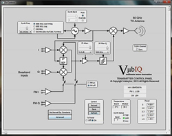
Figure 2 The control panel for the transmit board shows the block diagram, configuration and adjustable parameters.
The PEM003-KIT 60 GHz development system makes designing, optimizing and verifying a candidate system far easier than constructing one from “scratch.” It includes all hardware and software needed to construct a complete transmit – receive path. Through its simple yet comprehensive interface, system characteristics can be modified and verified using signal or spectrum analyzers, oscilloscopes or other instruments. It is a versatile platform capable of using a broad array of baseband signals that represent the higher-order modulation employed in common data systems. It also allows custom waveforms to be defined with software tools such as MATLAB.
Pasternack Enterprises
Irvine, Calif.
www.pasternack.com