
To this end, System Assembly and Modeling (SAM) has been introduced to version 2012 of CST STUDIO SUITE, providing an environment that simplifies the management of simulation projects in many ways. In SAM, a system is described by a schematic. In the simplest case this is a single block representing a parameterized 3D model. The user defines the desired evaluations for this model by setting up simulation tasks. SAM helps to compare the results of different solvers, or to model configurations within one simulation project.
The user can also set up a linked sequence of solver runs. For example, the electromagnetic analysis of a filter could be followed by a thermal simulation, then the filter's resulting mechanical deformation could be determined, and finally this geometric change could be used in another electromagnetic simulation to investigate the detuning effect. All simulations and links can be defined easily in SAM to enable a seamless multiphysics work flow.
By adding other models to the schematic, the user can create a 3D system. SAM helps the user to define the geometric alignment of the various components. Simulation tasks that include single or multiple components can be defined, and the user can specify which components should be simulated in 3D, and which solver and CST simulation acceleration options should be used for those simulations.
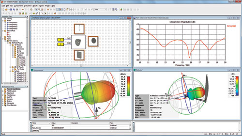
Figure 1 System Assembly and Modeling: various simulation projects can be derived from one master project.
Components could also be represented simply by their S-parameter behavior or by an equivalent field source in the system simulation. This combination of different levels of simulation helps to reduce the computational effort required to analyze a complex model accurately. Also, if required, SAM naturally enables the user to create and simulate their system in full 3D, as shown in Figure 1. In the figure, one project only includes a horn antenna; the other project also includes the reflector and ortho-mode transducer.
CST DESIGN STUDIO
The user accesses SAM through the familiar CST DESIGN STUDIO (CST DS) interface, which is part of every CST STUDIO SUITE installation, because it employs the CST DS task concept. This task concept has been enhanced significantly in version 2012. Most importantly, it enables the set-up of nested task structures to run, for example, optimization within parameter sweeps.
Accessing, sorting and filtering of the results data is greatly simplified by a new table view. CST DS 2012 also features a built-in component library that enables access to components from various vendors, such as ON Semiconductor and STMicroelectronics.
CST MWS Transient Solver
The well-established CST MWS transient solver has undergone many improvements, in particular with respect to material handling, for example for surface impedance, broadband constant tan(δ), and higher order dispersive magnetic materials, as well as transparent sheets. It also features a field-dependent material model, which allows the modeling of electric breakdown phenomena, such as ignition of RF plasma. The broadband sensitivity analysis with respect to geometry and material property variation has also been enhanced.
Bi-directional Coupling
Coupling between fields and complex cable bundles is bi-directional; cables can both receive and re-radiate electromagnetic fields. Depending on the routing/position of cables within an enclosure, the field distribution, modes and current paths can be strongly affected, and only considering one-way coupling may produce inaccurate results.
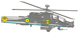
Figure 2 Model of a cable harness inside an Apache helicopter for EMP analysis: inset pictures show the cable cross-section at different locations.
CST STUDIO SUITE 2012 enables true transient bi-directional field/cable coupling to be simulated for complex cable bundles routed through complex 3D environments, such as electronics enclosures, aircraft and automobiles. Accurate analysis can be performed efficiently, despite the huge difference in scale between cable cross-section dimensions and overall system/vehicle dimensions. Figure 2 shows a model of a cable harness inside an Apache helicopter for EMP analysis.
FEM Fast Resonant Solver
With version 2012, a new fast resonant solver based on FEM has been introduced. It features curved elements of arbitrary order that enable a conformal representation of the geometry, which improves the simulation accuracy. The solver performs a model order reduction (MOR) and derives S-parameters and fields from this model. It outperforms the general purpose solver for applications that require a large number of samples for an accurate frequency sweep, such as higher order filters or structures designed for a very wide frequency band.
Eigenmode Solver
Alongside the Finite Integration Technique based Eigenmode solver, CST MWS now features an alternative Eigenmode solver, which uses the Finite Element Method. It also employs curved elements. In combination with the unstructured FEM grid, which can resolve small structure details very efficiently, it can increase the simulation performance dramatically.
Multi-layer Solver
CST MICROWAVE STUDIO (CST MWS) version 2012 comes with a new MoM solver, which solves planar, multi-layer geometries both accurately and efficiently. The layer stack can be generated automatically from 3D models. The geometry does not need to be strictly planar: 3D elements can also be included. Additionally, the solver features open boundaries and automatic edge mesh refinement, as well as automatic de-embedding of ports. Typical application areas are RF designs, such as planar antennas and filters, as well as MMIC and planar feed network designs. It can also plug-in to SAM.
Automatic Optimization
CST STUDIO SUITE features versatile algorithms for local and global optimization, such as the Nelder-Mead Simplex Method, Particle Swarm optimizers and the Trust Region Method, for which convergence can be further accelerated by employing sensitivity information. New to version 2012 is the CMA-Evolution Strategy, a powerful global optimizer with good convergence behavior.
HPC
High performance computing (HPC) continues to be a hot topic. The CST simulation acceleration scheme employs graphical processor units (GPU), clusters, or simply an array of computers in a network, to speed up simulations. New in version 2012 is support for Nvidia's latest GPU generation, not only by CST MWS but also by CST PARTICLE STUDIO, CST's software dedicated to the simulation of electron devices, such as traveling wave tubes and magnetrons.
The System Assembly and Modeling approach of CST STUDIO SUITE 2012 is entirely focused on simplifying electromagnetic system simulation by applying innovative simulation and optimization technology to either full EM systems or components thereof. This latest version includes a wide range of improvements that both increase speed and versatility and significantly enhance the user experience.
CST of America,
Framingham, MA
(508) 665-4400,
info@cst.com, www.cst.com